Overhead Crane Runway Design Guide: Beam Selection, Load Calculations & Alignment Standards
Published by: [Your Brand] Engineering Team | Last Updated: March 2026 | Reading Time: 9 min
Introduction
The runway is the backbone of every overhead crane system. It is the elevated rail structure along which the crane bridge travels — and it is also the element that most consistently separates a crane system that performs reliably for 30 years from one that develops alignment problems, wheel wear, and structural fatigue within five.
Yet runway design receives far less attention than crane selection in most facility planning processes. Buyers focus intensely on crane capacity, span, and hook height — and treat the runway as a procurement afterthought. The result is that runway deficiencies are among the leading causes of overhead crane operational problems: wheel flange wear from misaligned rails, rail walking from inadequate fastening, fatigue cracking at poorly detailed beam-to-column connections, and deflection-induced rail joint gaps that create shock loads on the traveling crane.
This guide provides the complete engineering framework for overhead crane runway design: the load types that must be accounted for, beam selection criteria and standard sections, deflection limits by crane service class, rail selection and fastening methods, alignment tolerances that govern crane performance, and the most common design errors that lead to premature maintenance costs. Whether you are a structural engineer specifying a new crane runway, a facilities manager evaluating an existing runway’s fitness for a new crane, or a procurement professional trying to understand what “runway engineering” actually involves, this guide gives you the technical foundation you need.
Part 1: Understanding the Loads a Crane Runway Must Resist
Unlike most building structural elements, crane runway beams experience complex, dynamic loading that changes with every crane movement. Designing for static loads alone is inadequate — and it is one of the most common errors in runway design by structural engineers without crane-specific experience.
Vertical Dead Load
The weight of the runway beam itself, the crane rail, rail clips, and any associated hardware (conductor bar brackets, end stop assemblies). This is the simplest load to calculate and the starting point for beam selection.
Vertical Live Load — Crane and Lifted Load
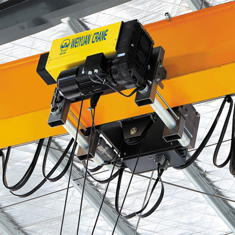
The maximum vertical wheel load imposed by the crane at any wheel position along the runway. This is the dominant load case for most runway beams and is calculated from the crane’s bridge weight, trolley weight, hoist weight, and the rated lifted load — distributed to the end trucks and then to the individual crane wheels based on the crane’s wheel spacing and the trolley’s position.
For a single-girder crane with two end trucks (each with two wheels), the maximum wheel load occurs when the trolley is positioned at the far end of the bridge, concentrating maximum load on the near-side end truck. CMAA Specification 70 provides the wheel load calculation methodology.
Impact Load (Dynamic Amplification)
When a moving crane bridge strikes its end stop, or when the hoist starts or stops a lift, the loads imposed on the runway are higher than the static values. Building codes and crane standards address this by applying an impact factor — typically 10 to 25% added to the static lifted load — to account for these dynamic effects. The AISC Design Guide 7 (Industrial Buildings) recommends applying impact factors to runway beam design per the applicable crane standard.
Lateral (Horizontal) Load — Crane Skew and Side Thrust
As the crane bridge travels along the runway, side thrust forces are transmitted to the runway rail from the crane wheels. These arise from:
- Imperfect wheel alignment (skewing of the bridge as it travels)
- Crane acceleration and deceleration forces
- Load swing during travel
CMAA Specification 70 quantifies lateral loads as a percentage of the maximum wheel load (typically 10 to 20%). These horizontal forces must be resisted by the runway beam’s top flange and the runway beam-to-column connection — which is why runway beam connections designed only for vertical loads are consistently problematic.
Longitudinal (Tractive) Load
When the crane drive motors accelerate or brake the bridge, longitudinal forces are transmitted through the crane wheels to the rails and into the runway structure. For most industrial cranes, these forces are smaller than the lateral loads and are typically the least critical runway load case — but they must be included in the connection design at runway beam splices and end stops.
Fatigue Loading
In production environments where the crane cycles hundreds of times per day, the runway structure experiences cyclic stress reversals that can initiate fatigue cracks at stress concentrations — particularly at welded connections. CMAA Specification 70 and the AISC Specification for Structural Steel Buildings both address fatigue design requirements for crane-supporting structures. For cranes in CMAA Class D, E, or F service, fatigue design governs many runway connection details and is not optional.
Part 2: Runway Beam Selection
Standard Beam Sections for Crane Runways
Crane runway beams are structural steel members selected to carry the loads described above within allowable deflection and stress limits. The following section types are commonly used:
Wide-flange (W-shape) beams with cap channels:
The most common runway beam configuration for light to moderate duty cranes. A standard W-shape beam is topped with a channel section (C-shape) to widen the top flange, which provides a wider bearing surface for the crane rail and improves the beam’s resistance to lateral-torsional buckling. The cap channel is welded to the top flange of the W-shape continuously or with intermittent welds per AISC Design Guide 7 recommendations.
Built-up plate girders:
For long-span runways and heavy-duty applications where standard W-shapes are insufficient, fabricated plate girders are used. The web plate, top flange plate, and bottom flange plate are individually sized for the required moment capacity, shear capacity, and deflection limit. Built-up girders offer greater design flexibility but are more expensive to fabricate.
Box girder sections:
Two-web box configurations are used for very heavy-duty crane runways (CMAA Class E and F) where resistance to torsion and lateral loading is critical. The closed section provides superior torsional stiffness compared to open W-shape or plate girder sections.
Beam Selection Criteria
The primary design criteria for crane runway beams are:
Bending stress: The maximum bending stress in the beam under the combined dead, live, and impact loads must not exceed the allowable bending stress for the steel grade used. The critical section is typically at midspan for uniformly supported beams.
Shear stress: The web of the beam must resist the maximum vertical shear at the support points. For heavily loaded short-span runways, shear can govern beam size.
Deflection: This is frequently the controlling criterion and is discussed in detail below.
Top flange local bending: The crane rail bears on the top flange of the runway beam, creating localized bending in the flange at the rail contact point. AISC Design Guide 7 provides the methodology for checking this condition, which can govern flange thickness selection for heavy wheel loads.
Fatigue: For cranes in CMAA Class D and above, the number of stress cycles over the crane’s design life can be several million cycles at the runway beam connections. Fatigue checks per AISC Appendix 3 (or the applicable fatigue standard for the project code) are required.
Part 3: Deflection Limits by Crane Service Class
Deflection limits for overhead crane runway beams are more stringent than those for typical building beams — because excessive deflection causes rail misalignment, increased wheel wear, and impact loading that degrades both the runway and the crane itself.
CMAA Specification 70 establishes the following vertical deflection limits for runway beams under full crane load (including impact):
CMAA Class A and B (standby/light service): L/600 maximum deflection
CMAA Class C (moderate service): L/600 to L/800
CMAA Class D (heavy service): L/800 to L/1000
CMAA Class E and F (severe to continuous): L/1000 or stricter
Where L is the span length of the runway beam between support points.
For a 30-foot span runway beam serving a Class D crane, the maximum allowable deflection under full load is 30 feet × 12 inches/foot ÷ 800 = 0.45 inches. A W18 beam that deflects 0.6 inches under this load would not be acceptable — a deeper, stiffer section must be selected.
Horizontal (lateral) deflection limits are also specified — typically L/400 for the runway beam’s resistance to lateral crane forces — to prevent the rail from being pushed laterally out of alignment by accumulated crane operations.
Part 4: Crane Rail Selection and Fastening
Rail Selection
Crane rails are specialized structural steel products specifically designed for crane runways. Standard structural rail sections are designated by weight per yard (ASCE rail standard) or by metric designation (A-series per DIN 536). Common sizes:
- ASCE 25 (25 lb/yard): Light duty runways, up to approximately 5-ton cranes
- ASCE 40 (40 lb/yard): Light to medium duty, 5 to 15-ton cranes
- ASCE 60 (60 lb/yard): Medium to heavy duty, 15 to 40-ton cranes
- ASCE 85 (85 lb/yard): Heavy duty, 40 to 100-ton cranes
- A100, A120, A150: Heavy and extra-heavy industrial applications
Rail selection is based on the crane’s maximum wheel load. Heavier wheel loads require harder, wider-head rails to prevent rail head deformation and provide a stable running surface for the crane wheels.
Rail Fastening Methods
Hook bolts (rail clips): The standard fastening method for industrial crane runways. L-shaped clips are welded to the runway beam top flange and hook bolts engage the rail foot, clamping it against the beam. This method allows the rail to be removed and replaced without modifying the beam, and accommodates minor rail misalignment correction through shimming.
Direct welding: Rail welded directly to the runway beam top flange. Provides maximum rigidity but prevents rail replacement without cutting. Rarely used in modern industrial installations due to its inflexibility.
Elastic rail fasteners: Spring-steel or elastomeric clip systems that allow controlled rail movement while maintaining alignment. Used on very high-speed runways and in applications where vibration isolation is important.
Joint plates (fishplates): At rail joints (splices between rail sections), joint plates bolted through both rails maintain alignment. For production cranes, welded rail joints (thermite welds) eliminate joint gaps that cause impact loading and are preferred for Class D and above applications.
Part 5: Alignment Tolerances and Their Impact on Crane Performance
Runway alignment is arguably the most important single factor in overhead crane longevity. Misaligned runways are the primary cause of wheel flange wear, premature end truck bearing failure, and crane skewing that accelerates structural fatigue.
ISO 12488-1 and CMAA Specification 70 establish the following alignment tolerances for crane runways:
Span tolerance (distance between rail centerlines at any point along the runway): ±5mm (±3/16 inch) from the nominal design span.
Rail elevation tolerance (difference in elevation between the two runway rails at any cross-section): ±10mm (±3/8 inch).
Rail straightness (lateral deviation of a single rail from its design centerline): ±3mm (±1/8 inch) over any 2-meter length.
Rail joint gap: Maximum 1mm (1/16 inch) for production cranes (Class C and above). Zero gap (welded joints) preferred for Class D and above.
Consequences of exceeding these tolerances:
- Span mismatch causes crane bridge skewing, which loads the wheel flanges against the rail head, generating lateral forces that wear both wheel flanges and rail heads rapidly.
- Elevation mismatch causes one end truck to carry disproportionately more load than the other, accelerating wheel and bearing wear on the overloaded side.
- Rail lateral deviation creates a sinusoidal travel path that the crane must constantly correct, increasing wear and causing vibration.
- Large rail joint gaps create impact loads every time a wheel crosses a joint, which fatigue both the rail joint hardware and the runway beam structure over time.
Part 6: Common Runway Design Errors to Avoid
Welding runway beams directly to supporting columns:
This detail transmits fatigue stress directly into the column-to-beam weld, which is subject to the full range of cyclic loading from crane operations. CMAA and AISC Design Guide 7 both strongly discourage welded beam-to-column connections for crane runways. Bolted connections with slotted holes (allowing for differential thermal expansion) are the preferred detail.
Ignoring lateral load in connection design:
Runway beam connections designed only for vertical loads will develop cracked welds or loose bolts in service as lateral crane forces cycle through the connection year after year. All runway connections must be designed for the combined vertical, lateral, and longitudinal load combinations.
Using standard structural beam sections without cap channels:
Standard W-shapes have narrow top flanges that provide minimal bearing width for the crane rail. The rail foot bears against a narrow flange, creating high localized bending stresses in the flange. Cap channel addition is standard practice for industrial crane runways for good reason.
Assuming existing columns can carry additional crane loads without structural analysis:
The temptation to hang a new crane runway from existing building columns without a formal structural analysis is significant — and consistently produces problems. Existing columns were designed for the original building loads only. Adding crane wheel loads, lateral side thrust, and dynamic impact loads frequently exceeds the original design margins. A licensed structural engineer must evaluate the existing structure before any new crane runway is attached to it.
Frequently Asked Questions
Q: How often should crane runway alignment be checked?
A: Runway alignment should be surveyed at initial commissioning (before the crane is placed in service), then annually as part of the periodic crane inspection, and whenever unusual wheel wear, skewing behavior, or rail walking is observed. For heavy-duty cranes (Class D and above) in continuous production use, semi-annual alignment surveys are recommended.
Q: Can I add a second crane to an existing runway?
A: Potentially — but it requires a complete structural re-analysis. The existing runway beams must be evaluated for the combined wheel loads of both cranes (including the case where both cranes are adjacent at the same runway section), the existing columns for the increased vertical and lateral loads, and the runway rail size for the highest wheel load crane. In most cases, adding a second heavier crane requires runway beam replacement or reinforcement.
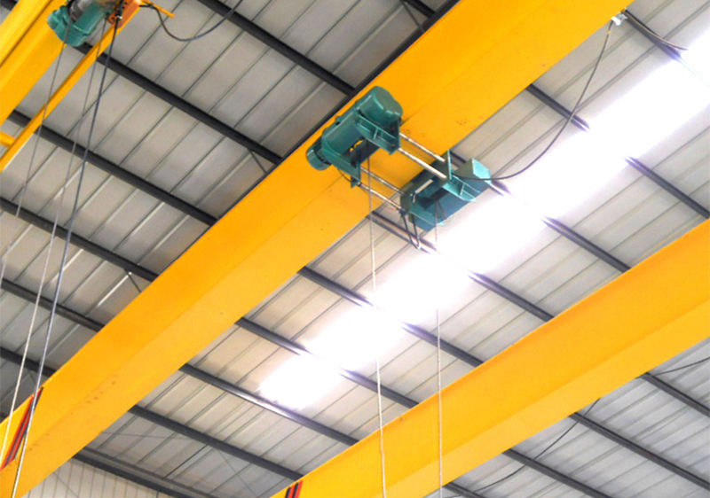
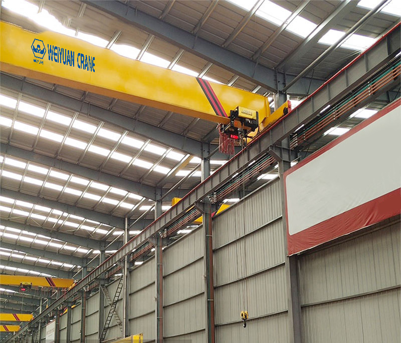
Q: What is the difference between top-running and underhung runway systems?
A: In a top-running system, the crane end trucks ride on top of the runway rails, placing the crane bridge above the rail level. In an underhung system, the crane bridge hangs below the runway beams, with the end trucks running on the bottom flange of the runway beam. Top-running systems provide greater hook height and can handle heavier loads. Underhung systems are used where existing building steel can serve as a runway or where lower headroom requirements apply.