


Jib Crane for Automotive & Machine Shop: Configurations, Capacity & Productivity Tips
Introduction
Automotive manufacturing and machine shop operations represent two of the largest and most demanding applications for jib cranes in industrial facilities. In automotive plants, jib cranes serve every stage of the production process — from engine assembly and body component tending to die change support and tooling fixture handling. In machine shops, they are the workstation crane of choice for loading and unloading CNC machining centers, lathes, grinders, and presses with the raw material and finished parts that keep production flow moving.
Both environments share a common challenge: lifting needs are concentrated at specific machines or assembly positions, loads range from precision-critical tooling components to heavy structural parts, operators need precise load positioning rather than just vertical lift capability, and production pressure means cycle time at every station matters.
Yet the specific jib crane configurations, capacity requirements, and productivity features that serve these two environments well differ in important ways. An engine assembly cell has different geometry, load characteristics, and precision requirements than a CNC turning cell or a stamping press die change station. Getting the configuration right for the specific application is the difference between a crane that genuinely improves throughput and one that operators avoid using because it does not fit the workflow.
This guide provides application-specific guidance for jib crane deployment in automotive and machine shop environments: the specific use cases, the right crane types and configurations for each, the capacity and control specifications that match the application demands, and the productivity best practices that get the most from every crane installation.
Part 1: Jib Crane Applications in Automotive Manufacturing
Application 1: Engine and Powertrain Assembly
Engine assembly is one of the most jib crane-intensive operations in automotive manufacturing. Every major engine component — block, crankshaft, cylinder head, transmission housing, differential assembly — must be precisely positioned on the assembly line fixture or engine stand. These components range from 50-lb cylinder heads to 800-lb assembled long blocks, with tolerances measured in fractions of a millimeter.
The jib crane at an engine assembly station must provide:
- Precise vertical positioning for setting components onto dowel pins and into bores where alignment is critical
- Controlled rotation capability to orient asymmetric components before lowering
- Adequate reach to access both the component staging rack and the assembly fixture without repositioning the crane
Best configuration for engine assembly:
- Capacity: 500 lbs to 1 ton, depending on the heaviest assembly handled at the station (fully assembled long blocks at major OEM facilities can exceed 700 lbs)
- Boom type: Standard straight boom or articulating boom where the hoist needs to reach over engine stand guarding or fixture structure
- Control: VFD-controlled electric chain hoist for smooth, micro-positioning capability — an across-the-line starting hoist creates vibration that can knock a partially assembled engine off its fixture
- Rotation: Low-friction slewing bearing essential for one-person operation; motorized rotation recommended for stations with high cycle rates (more than 30 assemblies per shift)
- Mounting: Floor-mounted with 360-degree rotation where the station has open floor access; wall-mounted where space constraints limit the footprint
Application 2: Stamping Press Die Changes
Stamping press die changes are among the most demanding jib crane applications in any manufacturing environment. Dies are precision-machined tooling — flat surfaces ground to micron tolerances — that weigh from 500 lbs to several tons depending on the press and the part being stamped. A die that is dropped, impacted, or set down roughly can suffer surface damage requiring costly regrinding.
The jib crane for die change service must provide:
- Smooth, shock-free hoisting with no sudden starts or stops — VFD hoist control is mandatory
- Adequate reach to access both the die storage rack (typically positioned adjacent to the press) and the press bed
- Hook approach that clears the press guarding, die spotting press, or overhead obstructions around the machine
- Precise positioning for seating the die into the press locating features
Best configuration for press die changes:
- Capacity: Sized to the heaviest die in the press room, plus 25% margin. For a press room handling dies up to 3 tons, a 4-ton jib crane is the appropriate selection.
- Boom type: Articulating jib crane is highly advantageous for press die change — the inner boom reaches over press guarding and the outer boom positions the hook directly over the die seat without requiring the crane structure to enter the press opening
- Control: VFD electric wire rope hoist for capacities above 2 tons; VFD electric chain hoist for lighter dies. The VFD is not optional — it is the safety requirement for die protection.
- Rotation: Motorized rotation recommended for any die change application above 2 tons where manually pushing a loaded boom creates significant operator effort
Application 3: Body Panel and Subassembly Handling
In body shop and trim assembly operations, jib cranes handle body panels, door assemblies, instrument panels, seat assemblies, and wiring harnesses that range from 20 to 300 lbs. These components are relatively light but are high-value painted or finished surfaces where any contact damage creates rework cost.
The challenge is control precision — the operator must position a finished surface component into a fixture or onto the body structure without contacting surrounding structure. Standard pendant control with an across-the-line hoist creates load swing that makes this precision difficult to achieve consistently.
Best configuration for body component handling:
- Capacity: 250 lbs to 1 ton
- Control: Intelligent assist (load-sensing) or VFD hoist — the goal is feather-light control at low hoist speeds for the final positioning phase
- Below-hook tooling: Vacuum lifters for flat panel surfaces, custom fixture lifters for irregular assemblies. The jib crane is the structure; the below-hook device is what actually engages the part, and it must be designed for zero surface damage.
- Rotation: Low-friction manual rotation is adequate for body assembly stations where the station geometry and work direction are well-defined
Application 4: Tooling and Fixture Handling in Assembly Plants
Automotive assembly plants contain thousands of tooling fixtures, gages, and assembly aids that must be moved, adjusted, and replaced periodically. These items range from 20-lb hand tools to 500-lb welding gun assemblies and 2,000-lb checking fixtures. A maintenance bay jib crane, combined with one or two strategically positioned production cell jib cranes, provides lift capability for tooling management throughout the facility.
Best configuration for tooling and fixture maintenance:
- Capacity: 1 to 2 tons covers most assembly plant tooling management needs
- Mounting: Freestanding floor-mounted for maintenance bay applications; wall or column-mounted for specific production cell positions
- Duty class: FEM M3 for maintenance bay cranes used several times per day; FEM M4 for production cell cranes with higher cycle rates
Part 2: Jib Crane Applications in Machine Shops
Application 1: CNC Machining Center Loading and Unloading
CNC machining centers — horizontal and vertical machining centers (HMC and VMC), turning centers, and multi-axis machining cells — are among the highest-value assets in any machine shop. Their productive utilization rate directly determines shop profitability, and any improvement in setup and load/unload cycle time translates directly to more machine hours per shift.
A jib crane at each CNC machine position provides:
- Ergonomic loading of billets, castings, and forgings that exceed manual handling limits (typically more than 35 to 50 lbs for most machine shop operators working repetitively)
- Precise positioning of workpieces into fixturing without the swing and instability of freehand rigging
- Faster cycle time versus coordinating a shared overhead crane for every load/unload
The CNC machining center presents specific physical challenges for jib crane configuration: machine guarding (OSHA-required safety enclosures around the cutting zone), pallet changers on HMCs that occupy the machine footprint at floor level, and chip conveyor discharge areas that constrain floor access.
Best configuration for CNC machining centers:
- Capacity: 500 lbs to 2 tons depending on the heaviest workpieces at the machine
- Boom type: Articulating jib crane is strongly preferred for CNC applications where the hoist must reach over the machine guarding door threshold and position the workpiece directly over the machine table or pallet — a straight boom physically cannot reach into the machine enclosure without the crane structure entering the opening, which is impossible with standard machine doors
- Control: VFD electric chain hoist for 500 lbs to 2 tons. Precise speed control at low hoist speeds is critical for seating workpieces into precision machining fixtures without impact.
- Reach: The articulating boom’s combined reach must extend far enough to place the workpiece at the machine table center from the crane’s mounting position outside the machine guarding footprint. This geometry must be verified for each specific machine model before specifying boom dimensions.
- Mounting: Floor-mounted (360-degree rotation) positioned to serve both the raw material staging area and the machine. Wall-mounted (180-degree) if column/wall access exists on the correct side of the machine.
Application 2: Lathe and Turning Center Loading
Manual loading of large lathes — placing long shafts, heavy rings, or large-diameter discs into the chuck — is one of the most ergonomically demanding tasks in machining. Parts weighing 50 to 500 lbs must be precisely aligned with the lathe spindle axis before the chuck is engaged, while the operator often stands in a constrained posture adjacent to the tailstock.
The jib crane for lathe loading must allow the operator to:
- Approach from the side (not blocking the operator’s access to the chuck and tailstock)
- Position the workpiece precisely on the lathe’s spindle axis
- Hold the workpiece steady while the chuck is engaged (the hoist must hold position precisely while the operator manipulates the chuck key)
Best configuration for lathe loading:
- Capacity: 500 lbs to 3 tons depending on the heaviest workpieces
- Boom approach direction: The crane should be positioned so the boom approaches the chuck area from above and to the side, not from directly in front of the lathe — this preserves operator access to the chuck and tailstock
- Control: VFD hoist that holds position reliably when the control is released — the operator needs both hands free to operate the chuck while the workpiece is suspended at load height
- Trolley: Push beam trolley adequate for most lathe loading applications — the load movement is primarily vertical during loading, with minor horizontal adjustment
Application 3: Surface Grinder and Cylindrical Grinder Workpiece Handling
Precision grinding workpieces are often heavy and require handling without surface damage — a workpiece that contacts the table surface at an angle can chip a ground surface that was dimensionally perfect. Jib cranes serving grinding machines are purely ergonomic and precision-protection devices; grinding workpieces are rarely heavy enough to create ergonomic risk from a NIOSH perspective, but they are often awkward (long, thin shafts or heavy, flat plates) that are genuinely difficult to handle manually without risking surface damage.
Best configuration for grinding machine workpiece handling:
- Capacity: 250 lbs to 1 ton
- Control: Intelligent assist or VFD hoist for feather-light positioning
- Below-hook tooling: Magnetic lifters for ferrous workpieces are standard; custom soft-jaw fixtures for non-ferrous precision components
Application 4: Press Brake, Punch Press, and Shear Material Handling
Sheet metal fabrication equipment — press brakes, punch presses, laser cutters, and shears — processes sheet and plate stock that is heavy, large in plan dimension, and sharp-edged. Manual handling of steel plate above 3/16 inch thickness in sheets larger than 4 × 4 feet creates significant ergonomic and injury risk from weight, edge contact, and awkward sheet geometry.
A jib crane with a magnetic lifter or vacuum lifter below the hook provides safe, one-person handling of sheet and plate stock at these machines.
Best configuration for sheet metal fabrication:
- Capacity: 1 to 3 tons depending on maximum plate size and thickness
- Below-hook: Electro-permanent magnet lifter for steel sheet/plate (preferred over electro-magnets because it does not require continuous power to hold the load); vacuum lifter for non-ferrous or stainless steel
- Control: Wireless radio remote allows the operator to stand beside the sheet during positioning — pendant cords become entangled in sheet metal handling more frequently than in other applications
- Rotation: Motorized rotation recommended — manually pushing a loaded 3-ton boom is ergonomically problematic for the operator performing this task many times per shift
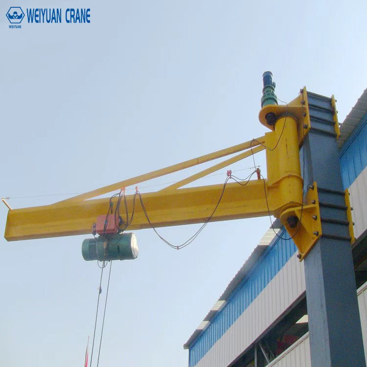
Weiyuan 500kg Wall Mounted Jib Crane
The Weiyuan 500kg Wall Mounted Jib Crane is a compact and efficient lifting solution designed for workshops, assembly lines, and warehouse operations. Mounted directly to a structural wall or column, it saves valuable floor space while providing smooth 180° slewing coverage for precise material handling up to 500 kg.
View Product / Get QuotePart 3: Productivity Best Practices for Jib Cranes in Automotive and Machine Shop Operations
Facilities that achieve the highest productivity from jib crane investments share these operational practices:
Integrate crane use into standard work: The jib crane must be specified in the standard work instruction as the required method for loads above the manual handling limit. Operators who can choose whether to use the crane will sometimes skip it under production pressure — this creates ergonomic risk and inconsistent cycle time.
Position the crane before buying it: Before ordering, physically mock up the crane’s pivot location in the workstation (using a floor mark and a tape measure to simulate the boom reach) and verify that the crane can reach every required load position without obstruction. This takes 30 minutes and prevents the most common crane misspecification mistake.
Specify the right below-hook tooling for the part: A generic hook is not adequate for most precision manufacturing applications. Dedicated lifting fixtures, vacuum cups, magnetic lifters, or soft-jaw gripper assemblies provide the controlled, damage-free load engagement that production quality requires.
Maintain boom slewing bearing lubrication: The number one operational complaint about jib cranes in production environments is that the boom is hard to swing. In most cases, this traces to an inadequately lubricated slewing bearing. Quarterly lubrication maintains the effortless rotation that makes the crane productive — an unlubricated bearing creates operator resistance to crane use.
Frequently Asked Questions
Q: Can one jib crane serve two adjacent CNC machines?
A: Sometimes, but this requires careful geometry analysis. If two CNC machines are positioned close enough that a single jib crane’s boom reach — from a pivot positioned between them — can reach both machine tables without repositioning, a shared crane can work. However, production scheduling conflicts (both machines needing the crane simultaneously at shift change) often make two dedicated cranes a better choice for high-utilization machines.
Q: What is the best jib crane configuration for a CNC turning cell with 6 machines?
A: For a cell with 6 turning centers in a U-shape or linear arrangement, a combination of dedicated articulating jib cranes at each machine (for individual workpiece loading) supplemented by a small overhead bridge crane covering the cell entry for raw material and finished part staging is typically the most productive solution. Each machine operator controls their own jib crane without competing for a shared resource.
Q: How do I specify the right articulating boom reach for my CNC machining center?
A: Start by measuring the distance from the proposed crane mounting location (outside the machine guarding footprint) to the machine table center. Add 12 to 18 inches of margin. The inner boom plus outer boom combined reach must equal or exceed this total distance. Also confirm that the inner boom length is adequate to clear the highest point of the machine guarding door opening when the outer boom is extended.