
Cranes
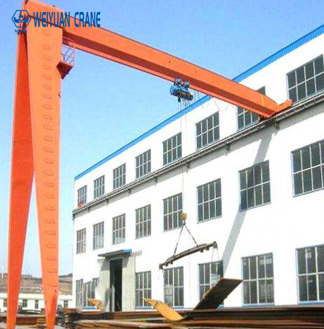
Gantry Crane for Hydropower & Dam Construction: Spillway Gate Handling, Penstock Installation & High-Altitude Operations
Introduction
Hydropower facilities represent some of the most challenging and technically demanding environments for gantry crane systems in the industrial world. The combination of extreme equipment weights, precision installation requirements, remote and high-altitude construction sites, permanent outdoor exposure to weather and water, and the critical safety consequences of any lifting failure in a dam or power plant environment creates a set of crane specification requirements that standard industrial equipment cannot meet without substantial adaptation.
Global hydropower capacity continues to expand — particularly in Asia, Africa, South America, and Central Asia — driven by renewable energy targets, energy security priorities, and the economic advantages of large-scale hydroelectric generation. Each new hydropower project, from small run-of-river plants to massive gravity dam developments, requires purpose-designed gantry crane systems for both the construction phase and the permanent operational lifecycle of the facility.
This guide provides the complete technical reference for gantry crane systems in hydropower and dam applications: the specific lifting requirements at each stage of dam construction and plant installation, the configurations used for different dam types and powerhouse layouts, the unique operational demands of dam-top and spillway gate cranes that serve the facility throughout its operational life, the high-altitude and remote site considerations that affect crane specification and logistics, and the maintenance requirements for cranes operating in the severe hydraulic environment of a dam facility.
Part 1: The Three Crane Phases of a Hydropower Project
Every major hydropower project requires gantry crane systems at three distinct phases, each with different requirements and — frequently — different crane configurations.
Phase 1: Civil Construction Cranes
During dam body construction, cranes serve the placement of formwork, reinforcement steel, and concrete equipment for gravity dams, arch dams, and embankment structures. The construction gantry crane must:
- Cover the full width of the dam body under construction
- Provide adequate hook height to reach the top of the dam as it rises through successive construction lifts
- Handle the loads of concrete bucket assemblies (typically 6 to 20 tons loaded), reinforcement steel bundles, and formwork panels
- Travel along the full dam axis length to serve the entire construction front simultaneously
Construction cranes for major dam projects are typically temporary installations — erected at the start of the civil works phase and removed or relocated when construction is complete. Rental crane solutions are common for this phase. Capacity typically ranges from 20 to 100 tons for standard gravity dam projects; arch dams and large gravity dams may require 150 to 300 ton capacity construction cranes.
Phase 2: Electromechanical Equipment Installation Cranes
Following civil construction, the powerhouse equipment installation phase requires cranes capable of handling the heaviest individual components of the power plant: turbine runners, generator rotors, main transformers, draft tube sections, spiral casing components, and penstock segments.
These are the heaviest lifts in a hydropower project. The largest Kaplan turbine runners for low-head projects exceed 500 tons. Francis turbine runners for high-head medium-capacity plants range from 50 to 300 tons. Generator rotors, wound with copper coils, range from 100 to 600 tons for large units. Main power transformers range from 50 to 300 tons per phase.
The overhead crane or gantry crane installed in the powerhouse machine hall must be sized for the heaviest single component installation — which is typically the generator stator or rotor. For a 500 MW unit, this may require a 500 to 700-ton overhead crane capacity. This installation crane typically remains as the permanent maintenance crane for the facility’s operational life.
Phase 3: Permanent Operational Cranes
The permanent cranes that serve a hydropower facility throughout its operational life include:
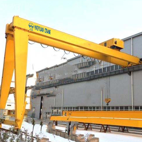
Dam-top gantry cranes (spillway cranes): Located along the top of the dam, serving to lower and raise spillway gates for flood discharge control and maintenance. These cranes operate outdoors permanently, subject to weather extremes from below-freezing winters to intense tropical heat and humidity. They must be reliable when called upon — often in emergency flood conditions when absolute reliability is non-negotiable.
Intake structure cranes: Serving the water intake structure to handle trash racks, stop logs, and intake gates that protect the penstock and turbine from debris and allow isolation for maintenance.
Powerhouse overhead cranes: Permanent machine hall cranes for turbine-generator unit overhaul, which occurs every 6 to 12 years per unit. These cranes must disassemble and reassemble the complete generating unit — lifting the rotor, runner, top cover, and all major components out of the draft tube pit and setting them on the machine hall floor for inspection and refurbishment.
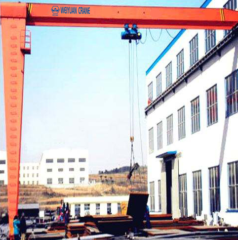
Part 2: Dam-Top Gantry Crane (Spillway Gate Crane) — Technical Requirements
The dam-top gantry crane is among the most technically demanding permanent outdoor gantry crane installations in any industrial sector. It must:
Operate Reliably in Emergency Conditions
Spillway gates are the primary flood protection mechanism for the reservoir. When reservoir levels approach flood stage during major storm events, the dam-top crane must lower spillway gates on demand — often at night, in high winds, and in heavy rain. The consequences of crane failure at this moment are potentially catastrophic for downstream populations and infrastructure.
Reliability provisions for dam-top cranes:
- Redundant hoist systems on critical gate cranes: dual independent hoists on a single bridge, either of which can complete the gate lowering operation independently
- Emergency power supply: battery backup or diesel generator connection that allows gate operation during grid power failure
- Wind speed interlocks: automatic stop systems that prevent operation in wind speeds exceeding the crane’s safe operating limit, with mandatory emergency lowering override capability for gate operations during storms
- Anti-corrosion specification for outdoor hydraulic environment: minimum C4 or C5 corrosion protection category per ISO 12944 for all structural steel in the water spray zone
Handle Gates of Extreme Weight and Dimensions
Spillway radial (Tainter) gates and vertical lift gates for major hydropower projects can be extremely heavy:
- Radial (Tainter) gate arms and skin plates: 20 to 200 tons per gate for large spillways
- Vertical lift stop log sections: 5 to 50 tons per section, multiple sections per gate slot
- Bulkhead gates for full reservoir head isolation: 50 to 500 tons for large-dam applications
The crane must handle the heaviest gate with adequate capacity margin, plus the weight of the crane’s own lifting beam and below-hook hardware. A crane serving 100-ton gates with a 15-ton lifting beam requires 120 ton rated capacity minimum (before applying the duty class capacity margin).
Provide Precise Gate Positioning
Seating a spillway gate accurately on its sill — with millimeter precision in a flowing water environment — requires hoist control capable of very slow, smooth lowering at the final approach. VFD hoist control providing 0 to 5% of full speed for the final meter of gate lowering is standard specification for dam-top cranes. Anti-sway systems that stabilize the gate against current forces during lowering are increasingly specified on cranes serving high-flow spillways.
Structural Design for Wind and Seismic Loading
Dam-top gantry cranes are exposed to the full design wind speed at the site — which for dam locations in mountain valleys or exposed ridgelines can reach 40 to 55 m/s (design storm conditions). The crane structure, runway, and foundation must be designed for these loads per the applicable national standard (GB/T 3811 in China, EN 13001 in Europe, ASME MH27.1 in North America, or project-specific standards).
In seismically active regions — which includes many of the world’s largest hydropower development zones in South and Southeast Asia, the Andes, and Central Asia — seismic load combinations must be included in the structural design. Dam-top crane foundations are typically integral with the dam structure itself, and seismic design must be coordinated with the civil design of the dam.
Part 3: Penstock and Turbine Installation — Lifting Requirements
Penstock Segment Handling
The penstock — the steel pipe that carries water under pressure from the reservoir to the turbine — is one of the most demanding components to install in a hydropower project. Individual penstock sections for large high-head plants can weigh 20 to 80 tons and measure 4 to 8 meters in diameter. The installation sequence requires:
- Transporting penstock sections from the laydown area to the intake/powerhouse connection
- Lowering sections into the penstock shaft or inclined tunnel
- Positioning each section for field welding to the previous section with millimeter alignment accuracy
Gantry cranes at the penstock laydown area handle the initial positioning and turning of sections as they arrive from fabrication. Access cranes at the shaft top handle the lowering sequence. The combination of heavy individual weights, long component dimensions, and precision alignment requirements makes penstock installation one of the most technically demanding crane operations in any construction project.
Turbine Runner and Generator Rotor Installation
The turbine runner installation is the critical lift of the entire electromechanical phase — setting the runner precisely on the turbine shaft, aligned to sub-millimeter concentricity tolerances, in a confined pit environment where the crane approaches from above through the machine hall floor opening.
Crane requirements for runner installation:
- Capacity: Sized for the heaviest runner + below-hook lifting frame (typically 10 to 30% above runner weight)
- Precision: VFD control providing approach speed of 0.1 to 0.5 m/min for the final lowering phase
- Anti-sway: Essential for maintaining runner concentricity during the final centering approach
- Load monitoring: Real-time load cell data during lowering to detect any binding or misalignment before the runner is fully seated
Part 4: High-Altitude and Remote Site Considerations
Many of the world’s most significant hydropower projects are located in remote mountain valleys at elevations of 1,000 to 4,000 meters above sea level. These locations impose crane specification and logistics requirements that are not encountered in standard industrial applications.
Altitude Effects on Electric Motor Performance
Electric motors operate at reduced efficiency and cooling capacity at high altitude because the thinner air provides less cooling for the motor windings and less air mass for convective heat transfer. As a rule of thumb, motor power capacity must be derated by approximately 1% per 100 meters above 1,000 meters altitude.
For a crane motor specified at sea level for a 100-ton lift, the same motor at 3,000 meters altitude has approximately 80% of its rated power capacity. The crane designer must specify motors with adequate power for the installation altitude — typically requiring one or two motor frame sizes larger than an equivalent sea-level installation.
Transportation to Remote Sites
Getting crane components to remote dam sites often requires transport over mountain roads with severe weight and width restrictions, or helicopter transport for the heaviest components. This logistical constraint directly affects crane design:
- Maximum component weight for road transport: often 40 to 80 tons per load on mountain roads
- Maximum component width: often 3.5 to 4.5 meters for mountain road transport
- Number of field splice connections: cranes for remote sites are designed with more field splices to break the structure into smaller transport units
The crane’s structural design must accommodate the transport constraint — either through bolted field splice connections that allow the structure to be assembled from transportable modules, or through the use of lighter-weight high-strength steel that reduces component weights while maintaining structural capacity.
Corrosion Protection in Hydraulic Environments
Dam-top and intake structure cranes are permanently exposed to water spray, mist, and humidity levels approaching 100% in the dam’s immediate environment. Standard industrial corrosion protection (C2 or C3 category per ISO 12944) is wholly inadequate for this exposure.
Minimum specification for cranes in the dam splash zone:
- Corrosion protection category: C4 (high) to C5-M (very high, marine/offshore)
- Surface preparation: Sa 2.5 (near-white blast cleaning) before any coating application
- Primer: Zinc-rich epoxy primer, minimum 60 microns DFT
- Intermediate coat: Epoxy intermediate, minimum 80 microns DFT
- Topcoat: Polyurethane topcoat, minimum 60 microns DFT
- Total system DFT: 200 microns minimum for C4; 300 microns minimum for C5-M
- Inspection: Film thickness measurement at each coat, holiday detection testing on completed system
Part 5: Maintenance Strategy for Operational Hydropower Cranes
Dam-top and powerhouse cranes may go years between major use — the spillway crane may not be operated for months or years between flood events, and the powerhouse overhead crane may not perform a major lift for 6 to 10 years between unit overhauls. Yet when they are needed, they must perform reliably on demand.
This intermittent-use, high-reliability requirement demands a maintenance approach different from production cranes that are used daily:
Regular exercising: ASME B30.2 and most hydropower facility operating procedures require that standby cranes be operated through a full functional test cycle — including load test under representative load — at least annually and before any anticipated major use event. A crane that has not been operated for 18 months before a flood event is a safety liability. Schedule annual functional tests as a mandatory facility maintenance activity.
Corrosion protection inspection: Annual inspection of the structural steel coating system, with spot repairs of any areas showing rust breakthrough. This is the most important maintenance activity for permanently outdoor hydraulic environment cranes. Deferred corrosion repair leads to structural section loss that cannot be reversed without full steel replacement.
Electrical system weatherproofing: Annual inspection of all electrical enclosures for seal integrity, internal condensation, and connection corrosion. Outdoor cranes in high-humidity environments suffer electrical failures from moisture ingress that do not occur in covered industrial cranes.
Brake and hoist overhaul: Even cranes that are rarely operated must have their hoists and brakes fully inspected and serviced at intervals based on time rather than use cycles — typically every 3 to 5 years regardless of the number of lifts performed. Lubricant degrades over time even without use; brake springs lose their calibrated force; seals harden and crack. Time-based maintenance intervals, not use-based intervals, govern standby crane service.
Frequently Asked Questions
Q: How long is the design service life of a dam-top gantry crane?
A: Dam-top gantry cranes are designed for a structural service life of 30 to 50 years — matching the operational life of the hydropower facility they serve. This long design life requires significantly more conservative fatigue design and corrosion protection specification than standard industrial cranes with 20 to 25-year design lives. The extended service life assumption is what justifies the C5 corrosion protection specification and the redundant mechanical design features that increase initial cost.
Q: What is the typical lead time for a custom hydropower gantry crane?
A: Custom dam-top and powerhouse cranes for major hydropower projects typically require 18 to 30 months from design approval to factory acceptance test completion. The engineering design phase alone takes 4 to 8 months for complex cranes with special environmental and seismic requirements. Procurement of long-lead components — main structural sections, large hoist assemblies, custom electrical systems — adds to the schedule. Hydropower project developers must initiate crane procurement well before the installation milestone to avoid becoming a critical path constraint.
Q: Can a dam-top gantry crane be designed to serve multiple gate types?
A: Yes — many dam-top cranes are designed to serve both the spillway radial gates and the intake stop logs with the same crane, using interchangeable lifting beams for each gate type. This multi-function design reduces the total number of permanent cranes required while maintaining full operational flexibility. The crane capacity and hook height must be sized for the most demanding individual lift across all gate types it will serve.