
What Is a KBK Crane? Complete Guide to Modular Light Rail Systems, Types & Applications
Introduction
KBK crane — you may have encountered this term while researching light-duty lifting solutions for a production workstation, assembly line, or warehouse operation. The letters KBK come from the German “Kombiniertes Baukastensystem” — Combined Modular System — a term that captures the defining characteristic of this lifting technology: a standardized, modular set of components that can be combined in virtually unlimited configurations to create lifting systems precisely matched to any workstation layout.
Originally developed by Demag Cranes & Components in Germany, the KBK system has become a global standard for light-duty industrial material handling. Today, KBK crane systems — and compatible modular light rail systems from various manufacturers — are installed in manufacturing facilities, assembly plants, warehouses, and cleanrooms across every industrial sector, typically serving loads from 125 kg to 5,000 kg where the flexibility, cost efficiency, and ergonomic performance of the modular rail approach outperforms traditional overhead crane solutions.
This guide provides the complete introduction to KBK crane systems: what they are and how they work, the major types and their differences, the key components that make up every KBK installation, the industries and applications where KBK systems deliver maximum value, how to choose between steel and aluminum rail systems, and the specification variables that determine which KBK configuration is right for your facility.
Part 1: What Is a KBK Crane System?
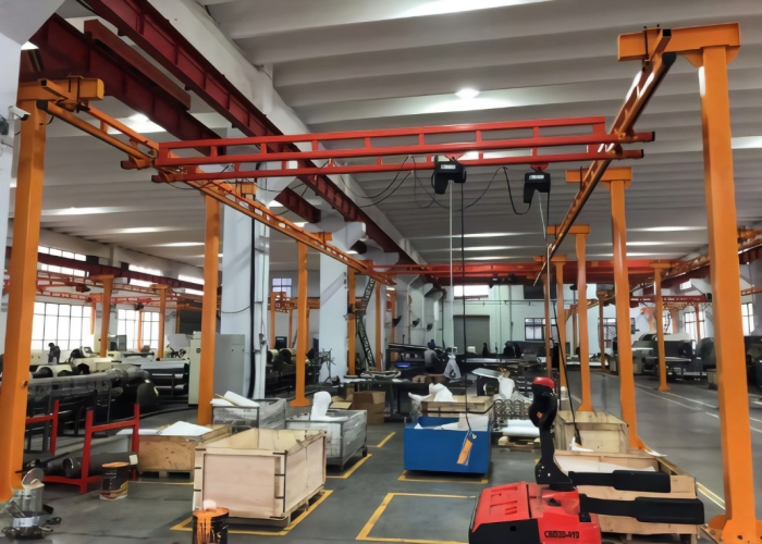
A KBK crane system is a modular light-duty overhead lifting system composed of standardized rail sections, suspension devices, traveling trolleys, and electric or manual hoists — all designed to be assembled by bolted connections without welding or special civil works.
The fundamental difference between a KBK system and a conventional overhead crane lies in its modular architecture. A conventional overhead crane is custom-engineered and fabricated as a single integrated unit for a specific span, hook height, and runway length. Changing the crane’s configuration — extending the runway, adding a branch line, changing the bridge span — requires significant engineering and fabrication work.
A KBK system, by contrast, is assembled from a catalog of standard components. Rail sections come in standard lengths that are bolted together to any required length. Switches, curves, and crossovers allow the rail to change direction or split into branches. The bridge span is set by the length of the cross-beam connecting the two runway rails. Any configuration change — adding a runway extension, creating a new branch, relocating a workstation — is a matter of adding, removing, or repositioning standard components, typically within a single maintenance shift.
The Three Axes of Movement
Like a conventional overhead crane, a KBK bridge crane system provides three independent motions:
Long travel: The crane bridge travels along the runway rails in the longitudinal direction — along the length of the work area. The bridge is suspended from trolleys that run on the bottom flange of the runway rail profiles.
Cross travel: The hoist trolley travels transversely along the bridge beam — covering the full width between the runway rails.
Hoisting: The electric or manual hoist raises and lowers the load vertically. The combination of these three motions gives the hoist access to any point within the rectangular coverage area of the bridge.
For monorail (single-rail) configurations, the system provides two axes of movement: long travel along the monorail and vertical hoisting. Cross travel is not available on monorail systems without a separate bridge.
Part 2: The Five Major Types of KBK Crane Systems
Type 1: KBK Monorail (KBK-I)
The simplest KBK configuration. A single rail suspended from the ceiling or supported by a floor-mounted frame carries a traveling trolley and hoist. The load moves along the rail path in one direction only.
Key characteristics:
- Capacity: 125 kg to 3,000 kg
- Coverage: Linear — load can be positioned anywhere along the rail length
- Rail paths: Straight, curved, with switches for branching and turntables for direction changes
- Applications: Material transport between fixed stations, assembly line feeding, machine loading/unloading where the load always travels in one direction
The KBK monorail’s ability to incorporate curves, switches, and turntables makes it particularly powerful for production line material flow — a single monorail system can loop through an entire production area, connecting multiple workstations in a single continuous overhead transport path.
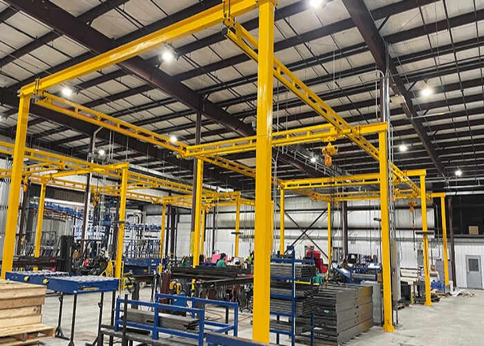
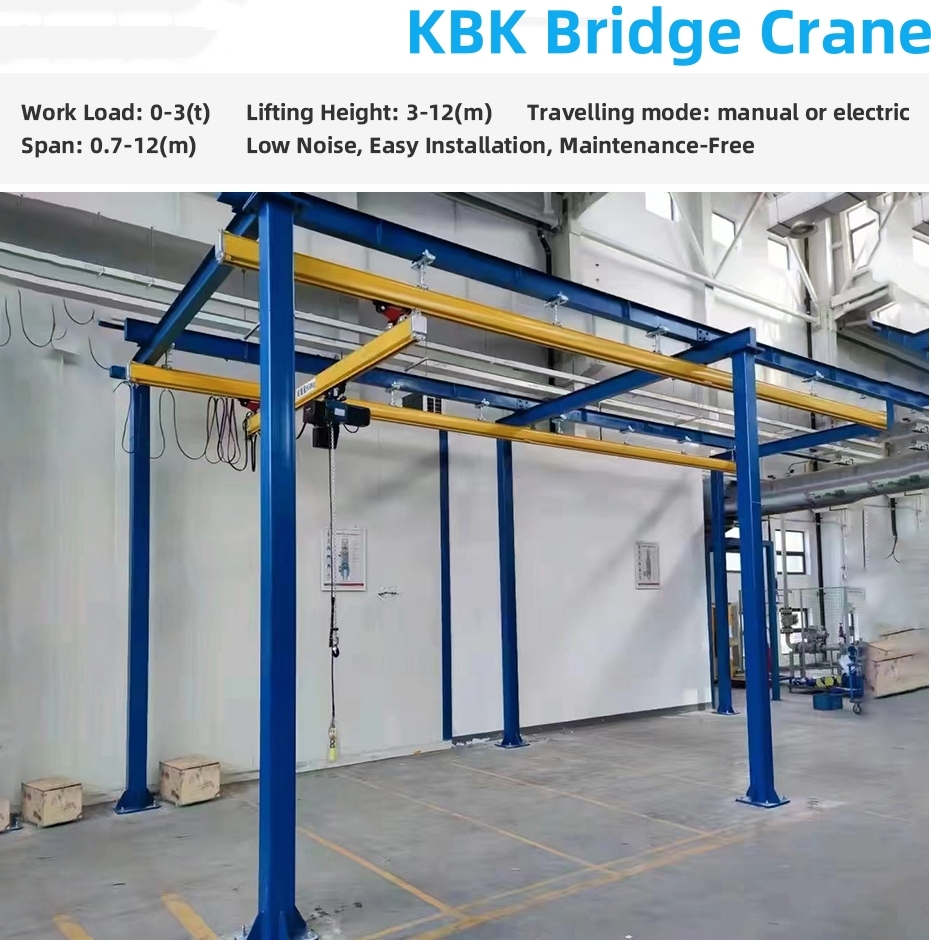
Type 2: KBK Single Girder Bridge Crane (KBK-II)
Two parallel runway rails plus a bridge beam spanning between them. The hoist trolley travels along the bridge, providing full rectangular coverage of the area beneath the crane.
Key characteristics:
- Capacity: 125 kg to 2,000 kg (standard); some designs to 3,200 kg
- Coverage: Full rectangular area beneath the bridge span
- Span: Typically 2 to 8 meters for standard bridge configurations
- Applications: Workstation material handling where two-axis coverage is required, assembly cell component feeding, machine tool loading and unloading
Type 3: KBK Double Girder Bridge Crane
Two parallel runway rails plus two parallel bridge beams. The hoist runs between the two bridge beams — providing better hook approach (lower minimum hook height) than single girder configurations.
Key characteristics:
- Capacity: 1,000 kg to 5,000 kg
- Coverage: Full rectangular area beneath the double bridge span
- Hook approach advantage: The hoist between the two girders allows the hook to be raised closer to the bridge structure, maximizing usable hook height in headroom-constrained facilities
- Applications: Heavier workstation handling, precision assembly of large components, applications requiring maximum hook height
Type 4: KBK Flexible (Suspension) Crane
The KBK flexible crane is a suspended single or double girder bridge crane where the bridge is suspended directly from the runway rails — there are no end carriages running on a separate runway. Instead, the bridge hangs from two trolleys that run on the ceiling-mounted runway rails.
This configuration provides the lowest possible installation profile — the crane fits within a very shallow overall height envelope — making it ideal for facilities with limited headroom. The bridge can be manually pushed along the runway or driven by an electric travel drive.
Key characteristics:
- Very low headroom requirement: the entire crane system (rails, bridge, hoist) fits within approximately 400 to 700mm of vertical space
- Smooth manual travel with low push force (typically less than 5% of lifted load for steel rail; even lower for aluminum)
- Capacity: 125 kg to 2,000 kg
Type 5: KBK Telescopic (Extending) Crane
A specialized KBK configuration where the bridge beam includes a telescoping section that can extend outward beyond the runway rail to reach loads that are positioned beside a column, wall, or machine housing that would block a standard bridge crane.
Key characteristics:
- Extends from one or both sides of the bridge center
- Allows the hook to reach positions that standard bridge cranes cannot access without crane repositioning
- Particularly valuable in machine tool loading where the machine column blocks straight bridge access to the spindle zone
- Capacity: typically 125 kg to 2,000 kg (limited by the extended cantilever moment)
Part 3: KBK Rail Materials — Steel vs Aluminum
KBK crane systems are available with two primary rail materials, each with distinct advantages for specific applications.
Steel KBK Rails
Standard cold-rolled steel profiles are the original KBK rail material and remain the choice for most general industrial applications.
Advantages:
- Higher load capacity per rail section — steel rails support heavier loads for a given span between suspension points
- Greater stiffness — less deflection under load, which improves trolley travel smoothness on long spans
- Lower cost for equivalent capacity compared to aluminum
- Proven service life of 20+ years in normal industrial environments
Best applications: General manufacturing, fabrication shops, warehousing, outdoor or semi-outdoor environments, applications above 1,000 kg
Aluminum KBK Rails
Extruded aluminum alloy rail profiles are increasingly specified for applications where the standard industrial environment requirements of steel rails are supplemented by specific functional demands.
Advantages:
- Significantly lighter than steel — aluminum rails impose much lower loads on the building structure or support frame. For facilities where the ceiling structure has limited load capacity, aluminum rails may make installation possible where steel rails would overload the structure.
- Corrosion resistant — aluminum’s natural oxide layer prevents corrosion in humid, wet, or mildly chemical environments without surface coating
- Cleanroom compatible — aluminum’s non-porous, non-corroding surface does not generate metallic particles or corrosion products. Combined with low-outgassing surface treatment, aluminum KBK rails are the standard choice for pharmaceutical, food processing, electronics, and semiconductor cleanroom applications.
- Easy cleaning — smooth aluminum surfaces are easy to wipe down with sanitizing chemicals, important in food and pharmaceutical environments
- Lower push force — aluminum extrusion profiles with smooth internal running surfaces and precision roller trolleys achieve lower rolling resistance than equivalent steel rail systems
Best applications: Cleanrooms (pharmaceutical, semiconductor, food), facilities with limited ceiling load capacity, stainless steel or aluminum hygienic environments, applications requiring frequent relayout or expansion
Part 4: Key Components of a KBK System
Rail Profiles
The rails are the structural backbone of the KBK system. Standard steel KBK rails use cold-rolled C-section or I-section profiles in several weight categories (KBK-I light series through KBK-III heavy series) that correspond to different load capacity ranges. Aluminum rails use extruded profiles engineered specifically for the KBK application.
Rail sections are produced in standard lengths (typically 500mm to 6,000mm) that are bolted end-to-end to achieve any required runway or bridge length. Rail joints use precision-machined alignment sleeves that maintain smooth transitions between sections — eliminating the step at the joint that would otherwise cause trolley impact loading.
Suspension Devices
The suspension system connects the rails to the building ceiling, roof structure, or support frame. KBK suspension hardware includes adjustable rod suspensions, clamp-type beam attachments, and adjustable height hangers that allow the rail elevation to be set precisely during installation and adjusted as needed.
The building structure at each suspension point must carry the rail dead load plus the dynamic crane load per suspension point. Load calculations are provided in the KBK system’s technical documentation for each rail series and suspension spacing.
Trolleys
Trolleys are the wheeled assemblies that travel along the bottom flange of the rail. KBK trolleys are available in:
- Manual push trolleys: The operator pushes the load to position it. Very low rolling resistance makes manual operation practical for loads to 500 kg on flat rail.
- Electric travel trolleys: Motor-driven travel for higher loads or longer distances where manual pushing is impractical. VFD control provides smooth acceleration and precise stopping.
- Chain-driven trolleys: An intermediate option using a hand chain to drive the trolley for moderate loads where electric travel is not justified.
Hoists
The hoist is the vertical lifting mechanism. KBK systems accept all standard electric chain and wire rope hoists within the rail’s rated capacity:
- Electric chain hoists: Standard for KBK applications up to 2,000 kg. Compact body dimensions that minimize headroom consumption. Low purchase cost.
- Manual chain hoists: For very low frequency applications or where electrical power is not available at the crane location.
- Pneumatic hoists: For explosion-proof or compressed-air-powered applications.
- Intelligent assist hoists: Load-sensing control systems that respond to operator force rather than button commands — transforming the KBK crane into an ergonomic assist device for precision handling.
Part 5: Industries and Applications
KBK crane systems serve the widest range of applications of any overhead lifting system category. Representative applications by industry:
Automotive manufacturing: Engine and transmission assembly workstations, body panel handling between stamping and welding, trim component distribution along assembly lines, and maintenance bay engine removal.
Electronics and semiconductor: Wafer carrier handling in cleanroom fabrication areas (aluminum rail, cleanroom-grade components), PCB assembly line component feeding, test equipment positioning.
Pharmaceutical and food processing: Ingredient and raw material handling in GMP production areas, mixing vessel lid handling, filling line container transfer, finished product packaging transfer.
Mechanical engineering and fabrication: Machine tool loading and unloading (CNC machining cells, turning centers, surface grinders), weldment positioning at welding workstations, assembly station component supply.
Logistics and warehousing: Order picking assist in high-density storage areas, goods-to-person picking station material handling, returns processing workstation lifting.
Frequently Asked Questions
Q: What does KBK stand for?
A: KBK stands for “Kombiniertes Baukastensystem” — German for “Combined Modular System.” The term was coined by Demag Cranes & Components, the German company that developed the original KBK light rail system. Today, “KBK” is widely used as a generic term for modular light rail crane systems from multiple manufacturers, not exclusively Demag products.
Q: What is the maximum capacity of a KBK crane?
A: Standard KBK systems typically support loads from 125 kg to 5,000 kg. The most common working range is 250 kg to 2,000 kg. Heavy-duty KBK variants extend to 5,000 kg for double girder configurations. Above 5,000 kg, conventional overhead cranes or gantry cranes are more cost-effective than KBK systems.
Q: Can a KBK system be expanded after installation?
A: Yes — expandability is one of the KBK system’s primary advantages. Adding runway length requires additional rail sections bolted to the existing runway end. Adding branch lines requires installing a switch section at the branch point. Changing the bridge span requires substituting a longer bridge beam. None of these modifications require welding, drilling into existing structure, or significant production downtime. This makes the KBK system particularly valuable in facilities that anticipate future layout changes or production expansion.
Q: Does a KBK crane require a building permit or structural engineering approval?
A: The building structure — ceiling, roof beams, or dedicated support frame — must be capable of carrying the suspension point loads. For ceiling-mounted installations, a structural engineer should verify the ceiling or beam capacity before installation. In most jurisdictions, installing a KBK system in an existing building requires a building authority notification or permit; requirements vary by location. Your KBK supplier should provide suspension load data for all planned suspension points to facilitate the structural review.