
Semi-Gantry Crane (Half-Portal) Guide: When One Leg Is Enough & How Wall-Support Designs Save Space and Cost
Introduction
Most facilities that need a gantry crane think in terms of two options: a full portal gantry crane with two floor-mounted legs, or an overhead bridge crane suspended from the building structure. The semi-gantry crane — also called a half-portal crane — occupies a practical middle ground between these two configurations that is often overlooked during the planning stage, yet is the most cost-effective and space-efficient solution for a significant number of real-world applications.
A semi-gantry crane uses one floor-mounted leg on one side of the working area and attaches to the building’s wall, column, or a dedicated wall-mounted runway beam on the other side — eliminating the foundation, leg, and floor space that a second freestanding leg would require. The result is a crane that provides the same rectangular working coverage as a full gantry crane at 15 to 30% lower total installed cost, with one less obstruction at floor level and without placing the same structural demands on the building that a full overhead bridge crane runway requires.
This guide provides the complete technical reference for semi-gantry cranes: the structural principles that make the single-leg design work, the four application scenarios where semi-gantry configuration is the optimal choice, the comparison framework against full gantry and bridge crane alternatives, the key structural design parameters, and realistic 2026 price references.
Part 1: Structural Principle — How the Half-Portal Works
Full Portal vs Semi-Gantry: The Core Structural Difference
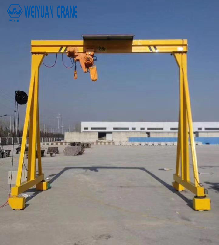
A full portal gantry crane has two vertical legs, one on each side of the working area, each carrying approximately half the combined vertical load of the crane bridge, trolley, hoist, and lifted load to the ground through independent floor-mounted foundations. The structure is symmetric and self-contained — it places no lateral loads on any building element and can be installed in any location where floor foundations are feasible.
A semi-gantry crane has one vertical leg (the “free leg” or “low leg” side) that carries its loads to the floor through a conventional foundation, and one side where the crane bridge connects directly to a wall-mounted runway rail, a building column, or a dedicated structural bracket (called a corbel or haunched bracket). This wall-mounted connection carries the vertical load component and a horizontal force component from the crane bridge’s movement to the building structure.
The structural logic is straightforward: the building wall or column already exists as a structural element. If it has adequate capacity to carry the additional crane loads, using it as one side of the crane’s support system eliminates the cost and floor space of a second independent leg entirely.
Single-Leg Side: Foundation Design
The floor-mounted leg of a semi-gantry crane carries the full asymmetric loading that results from the crane lifting a load at any position across the bridge span. When the load is directly above the floor-mounted leg, that leg carries maximum vertical load and minimum overturning moment. When the load is directly above the wall-mounted side, the floor-mounted leg carries a reduced vertical load but must resist a significant overturning moment created by the load’s offset from the leg centerline.
This overturning moment — greater than what either leg of a full portal crane must resist individually — is the critical design load for the semi-gantry’s floor-mounted foundation. The foundation must be deeper and larger in diameter than an equivalent full portal crane leg foundation to resist this moment. Foundation design must use the crane manufacturer’s published asymmetric foundation loads rather than the symmetric load data provided for full portal configurations.
Wall-Mounted Side: Connection Types
Three connection configurations are used for the wall-mounted side of a semi-gantry crane, depending on the building structure available:
Direct wall rail mounting: A crane runway rail is bolted directly to a reinforced concrete wall through anchor bolts embedded in the wall. The wall must be structural — reinforced concrete with adequate section and reinforcement to carry the vertical crane loads as a series of point loads along the runway length, plus the horizontal forces from crane travel acceleration and braking.
Column-mounted bracket (corbel): A structural steel or concrete bracket (corbel) is attached to existing building columns at the required runway elevation. The runway rail is mounted on the brackets, which transfer the crane loads directly to the column rather than to the wall between columns. This approach is more structurally efficient than direct wall mounting because building columns are specifically designed for concentrated loads.
Dedicated wall beam: A structural steel beam is installed along the building wall, spanning between columns and supporting the runway rail at the required elevation. This approach provides the most flexibility in runway positioning and is used when neither the wall nor existing column brackets provide the required load capacity.
Equal Height vs Unequal Height Semi-Gantry
Standard semi-gantry cranes have the runway rail at the same elevation on both sides — the floor-mounted leg and the wall-mounted side both position the crane bridge at the same height. This equal-height configuration is most common and produces the simplest structural design.
Unequal-height semi-gantry cranes position the floor-mounted leg runway at a different elevation from the wall-mounted runway — typically with the wall-mounted side at a higher elevation to allow clearance for equipment, personnel, or vehicles to pass under the low side of the bridge at the wall. This unequal configuration creates an asymmetric bridge structure that requires specific engineering for the inclined bridge geometry and the different support reactions at each end.
Part 2: Four Application Scenarios Where Semi-Gantry Is the Optimal Choice
Scenario 1: Factory with One Structural Wall and One Open Side
The most common semi-gantry application: a facility where one side of the working area is adjacent to a structural concrete or masonry wall with adequate capacity to support crane loads, and the other side is an open floor area where a full second leg would obstruct material flow, vehicle access, or equipment positioning.
A fabrication shop where heavy weldments are produced along one wall, with forklift access required across the floor in front of the work area, is a classic example. A full gantry crane’s second leg would block the forklift lane; a bridge crane would require significant building structural upgrades; a semi-gantry with the wall as one support provides the crane coverage without the obstructions.
Scenario 2: Building Renovation with One Adequate Column Row
When an existing facility is being retrofitted with an overhead crane for the first time, the building’s structural columns rarely have capacity for a full bridge crane runway load on both sides. However, one column row may have adequate capacity for the crane loads after engineering assessment, while the opposite column row does not.
In this scenario, a semi-gantry configuration — using the adequate column row as the wall-mounted side and installing a new floor-mounted leg on the opposite side — allows a functional crane installation without the cost of reinforcing the second column row to bridge crane runway capacity. The single new foundation on the floor-mounted side is typically 40 to 60% cheaper than the structural upgrades that would be required to convert the second column row for bridge crane service.
Scenario 3: Yard or Dock Boundary Operations
Outdoor semi-gantry cranes are frequently used at loading docks, quaysides, and storage yard boundaries where the crane must reach over the edge of the structure — one side of the crane operates over the dock/quay face and the other side is within the storage yard. A full portal crane in this configuration would require two floor foundations, both of which are difficult to construct near the dock edge. A semi-gantry with one leg set back from the edge and the other side using a wall-mounted rail on the dock structure eliminates the foundation at the difficult dock-edge location.
Scenario 4: Asymmetric Coverage Requirements
Some applications require crane coverage that is not centered on the working area — one side needs more coverage than the other, or the crane must cantilever significantly beyond one runway. Semi-gantry configurations can be designed with a cantilever extension on the low-leg side, providing additional reach beyond the floor-mounted leg without requiring another foundation. This asymmetric coverage is more easily achieved with a semi-gantry than with a full portal crane.
Part 3: Selection Comparison — Semi-Gantry vs Full Portal vs Bridge Crane
Semi-Gantry Crane vs Full Portal Gantry Crane:
Cost: Semi-gantry is 15 to 30% less expensive than full portal at equivalent capacity and span, primarily from eliminating one foundation and one leg structure. However, the wall structural assessment and any required wall reinforcement partially offset this saving.
Floor space: Semi-gantry eliminates one leg’s floor footprint — typically a 400 to 800mm diameter foundation pad at floor level. In tight floor layouts, this single leg elimination can be the decisive factor.
Installation: Semi-gantry installation is somewhat more complex than full portal because the wall connection requires structural engineering assessment and often involves anchor work in an existing concrete or masonry wall.
Structural requirement: Full portal places no structural demands on the building; semi-gantry requires the wall or column to carry crane loads — a constraint that eliminates the semi-gantry option in buildings with inadequate wall structure.
Semi-Gantry Crane vs Overhead Bridge Crane:
Building structure requirement: An overhead bridge crane requires both column rows (or equivalent runway supports) to carry crane runway loads — typically the more demanding structural requirement. A semi-gantry requires only one wall/column to carry crane loads — a less demanding requirement that may be feasible in buildings where full bridge crane runway installation is not.
Hook height: Bridge crane provides maximum hook height by using the full building clear height; semi-gantry consumes height for the floor-mounted leg but provides more hook height than a bridge crane in buildings with low roof structure near the wall.
Cost: Semi-gantry is typically less expensive than an equivalent bridge crane installation when the building structural upgrade costs are included.
When semi-gantry is the only viable option: When the floor cannot accept two independent foundations (due to underground utilities, excavation limitations, or existing floor structures) AND the building has one adequate structural wall — the semi-gantry may be the only technically feasible overhead crane solution.
Part 4: Key Structural Design Parameters
Floor-Mounted Leg Foundation Loads
The asymmetric loading of a semi-gantry crane creates a foundation load profile that differs significantly from a full portal crane. The crane manufacturer must provide:
Maximum vertical load: The downward force at the floor-mounted leg under the worst-case loading condition — typically when the hoist is positioned directly above the wall-mounted side with the maximum rated load, creating maximum uplift tendency at the floor-mounted leg.
Maximum overturning moment: The moment at the leg base resulting from the asymmetric load position. For a 10-ton semi-gantry with a 15-meter span and the load at the wall-mounted side, the overturning moment at the floor-mounted leg base can exceed 150 ton-meters — significantly higher than what a symmetric full portal leg foundation would need to resist.
These values must be provided by the crane engineer based on the specific crane geometry and rated capacity — they cannot be estimated from catalog data for full portal cranes.
Wall-Mounted Side Structural Assessment
Before any semi-gantry crane is specified, a licensed structural engineer must verify that the wall, column, or dedicated runway beam on the wall-mounted side can carry the crane’s imposed loads:
Vertical reaction: The vertical load at the wall connection under maximum loaded crane conditions.
Horizontal longitudinal force: The force parallel to the runway from crane travel acceleration and braking.
Horizontal lateral force: The force perpendicular to the runway from wheel flanges during crane travel.
For direct wall mounting on concrete: The wall section, reinforcement, and anchor bolt embedment must be verified against these loads using the applicable structural design code (ACI 318 for concrete in North America; EN 1992 in Europe).
Bridge Beam Design for Asymmetric Support
The semi-gantry bridge beam spans between the floor-mounted leg and the wall-mounted connection point. Unlike a full portal crane where both ends have identical support conditions, the semi-gantry bridge has different support stiffness at each end — the floor-mounted leg has some rotational flexibility, while the wall-mounted connection may be essentially rigid or may have significant flexibility depending on the connection design.
This support condition asymmetry affects the bridge beam’s structural behavior — particularly the distribution of bending moments along the span under asymmetric trolley load positions. The crane engineer must account for these asymmetric support conditions in the bridge structural design; standard portal crane bridge designs do not apply directly to semi-gantry configurations.
Part 5: Installation and Commissioning
Track Height Differential Control
For equal-height semi-gantry cranes, both runway rails must be installed at the same elevation — within ±3mm of each other when measured at any cross-section along the runway. Greater height differential causes the bridge to travel in a skewed attitude relative to the runway, imposing lateral forces on the wheel flanges and creating uneven wheel loading that accelerates wear.
Use precision laser leveling during rail installation, with rail height verified at both the floor-mounted leg rail and the wall-mounted rail before the bridge is installed.
Wall-Mounted Rail Anchor Installation
Anchor bolts for the wall-mounted runway rail in concrete walls must be installed to the structural engineer’s specification — embedment depth, bolt diameter, and edge distance are all structurally determined values that cannot be substituted with “equivalent” hardware. Use calibrated torque application on all anchor nuts and verify anchor installation with pull-out testing as specified by the structural engineer.
Expansion anchors are acceptable for light-duty semi-gantry applications; chemically bonded (epoxy) anchors are required for medium and heavy-duty applications where the anchor loads approach the expansion anchor’s rated capacity.
Bridge Level Verification After Installation
After the bridge is installed on both runways, verify the bridge’s lateral level (the angle of the bridge girder relative to horizontal in the cross-span direction) using a precision level instrument on the bridge’s top or bottom flange. A bridge that is not level in the cross-span direction runs with the trolley tending to drift toward the low end — a safety and operational quality issue.
Part 6: 2026 Price Reference
Semi-gantry crane prices (FOB manufacturer, single girder unless noted, including one floor-mounted leg and hardware for wall-mounted connection):
5-ton, 12-meter span, FEM M4: $18,000 to $38,000
10-ton, 15-meter span, FEM M4: $32,000 to $65,000
20-ton, 18-meter span, FEM M4-M5: $60,000 to $120,000
32-ton double girder, 20-meter span, FEM M5: $110,000 to $200,000
Comparison to full portal crane at equivalent specification: Semi-gantry typically 15 to 25% less expensive on crane-only price.
Foundation cost saving: Eliminating one floor-mounted foundation saves $3,000 to $15,000 depending on soil conditions and crane capacity — partially offset by the cost of wall structural assessment ($500 to $2,000) and any required wall reinforcement ($2,000 to $20,000 depending on findings).
Net typical saving versus full portal: 10 to 20% of total installed cost, with the saving being largest when the existing wall structure is adequate without reinforcement.
Frequently Asked Questions
Q: Can any concrete wall support a semi-gantry crane?
A: No. The wall must be structural — designed and constructed to carry concentrated loads from the crane. Partition walls, curtain walls, infill masonry between structural columns, and any wall not specifically designed as a load-bearing structural element cannot support semi-gantry crane loads without engineering assessment and likely reinforcement. A licensed structural engineer must verify wall capacity from structural drawings and, if needed, from core sample testing before a semi-gantry installation proceeds.
Q: Is a semi-gantry crane less stable than a full portal crane?
A: A correctly designed semi-gantry crane, with an adequately sized floor-mounted foundation and verified wall connection, is structurally safe and stable for its rated capacity. The structural behavior differs from a full portal crane — the asymmetric loading creates higher foundation moments — but these differences are accounted for in the engineering design. The stability concern is ensuring that the engineering is done correctly, not that the configuration is inherently less safe.
Q: Can a semi-gantry crane be converted to a full portal crane later?
A: Yes — adding a second leg and foundation on the wall-mounted side converts the semi-gantry to a full portal configuration. This is a viable upgrade path if the facility’s requirements grow beyond what the existing wall structure can support, or if the wall connection needs to be eliminated for any reason. Design the floor-mounted leg’s structural steel with standard connection points that would accept a second leg attachment without modification.