
Jib Crane Workstation Design Guide
Introduction
Most jib cranes that underperform in production do not have the wrong capacity. They have the wrong geometry. The boom is too short to reach one critical position. The rotation arc stops 20 degrees short of the deposit point. The crane is installed 600mm too far from the machine spindle centerline. The operator has to swing the load past the safe zone to reach the fixture.
These problems share a common cause. The crane was selected before the workstation was analyzed. The buyer chose a standard catalog size. Nobody verified it against the actual floor layout.
A correctly designed jib crane workstation starts with the workspace — not the crane catalog. Four analysis steps before ordering eliminate the vast majority of post-installation problems. This guide walks through every step, from workstation analysis to hoist selection to ergonomics, with practical tools you can apply to your own production cell.
Part 1: Workstation Analysis — Four Steps Before Selecting the Crane
Do these four things before opening a crane catalog. They take less than an hour. They prevent expensive post-installation regrets.
Step 1: Draw the Workstation Floor Plan to Scale
Sketch or CAD the workstation footprint. Include the machine tool, fixtures, staging areas, incoming material locations, and outgoing material destinations. Use actual measured dimensions — not estimates.
Mark every position where the crane hook must reach. Label each one: “raw material pickup,” “machine load point,” “finished part deposit,” “inspection station.” These are the crane’s required coverage points.
Step 2: Measure the Maximum Reach Distance
Find the proposed crane mounting location on the floor plan. Measure the distance from that point to every required coverage position. The farthest coverage point determines the minimum boom length.
Add a margin. Booms that just barely reach the farthest point leave no room for layout changes or load rigging adjustments. Add 300 to 500mm to the measured maximum reach for the minimum specified boom length.
Step 3: Determine the Required Rotation Arc
With the mounting point established, draw all required coverage positions on the floor plan. Measure the full angular range from the nearest position to the farthest position around the mounting point.
That angular range is the minimum rotation the crane must provide. Round up to the nearest standard rotation option: 180°, 270°, or 360°.
Check for obstructions. Building columns, machinery, conveyor systems, and walls may limit actual rotation even if the crane’s mechanical design allows more. Mark any obstruction on the floor plan. Verify that the required coverage arc is achievable without structural interference.
Step 4: Confirm the Operator’s Standing Position
The crane’s mounting point and boom geometry must serve the operator — not the other way around. Identify where the operator stands during each material handling step. Verify that the pendant control or wireless remote is accessible from all operator positions. Confirm the operator does not need to step into the load swing zone to complete any step.
This step prevents the common problem of a crane that technically covers all required positions but forces the operator into unsafe or ergonomically poor postures to use it.
Part 2: Boom Length and Coverage Radius
How the Coverage Area Works
A jib crane’s working envelope is a sector — a slice of a circle. The radius equals the boom length. The arc equals the rotation angle. The crane can position a load anywhere within that sector.
The effective working radius is slightly less than the boom length. The hoist trolley cannot reach the very end of the boom — it stops at the approach distance from the boom end (typically 200 to 400mm depending on the hoist model). It also cannot reach closer than the minimum approach distance from the mast (typically 400 to 600mm from mast centerline).
Effective working radius = boom length − end approach distance
Minimum reach from mast = minimum approach distance
Verify both values against your required coverage positions. A required position at 5.8 meters from the mast with a 6-meter boom and 350mm end approach distance is unreachable — effective radius is only 5.65 meters.
Verifying Coverage on the Floor Plan
Draw a circle centered at the mounting point. Set the radius equal to the effective working radius. Draw radial lines at the limits of the required rotation arc.
Every required coverage position must fall within the resulting sector. If any position falls outside the sector, increase the boom length or adjust the mounting point location.
This graphic check takes 5 minutes. It catches reach and coverage problems before the crane is ordered.
The Cost of an Oversized Boom
Selecting a longer boom than necessary is tempting. More reach feels like more capability. But a longer boom has real costs beyond the catalog price.
A longer boom creates a larger overturning moment at the mast base. This requires a larger foundation or stronger wall mounting. It also reduces the allowable load at the boom tip for cranes with variable load ratings. And it increases the tip deflection and load swing — making precise positioning harder, not easier.
Specify the minimum boom length that covers all required positions with appropriate margin. Not the maximum available.
Part 3: Rotation Angle Selection
180° — Wall-Mounted Standard
A wall-mounted jib crane provides approximately 180° of rotation. The wall behind the crane limits the arc to the half-circle in front of it.
This is the correct choice when all required coverage positions are in front of the crane. It works well for workstations positioned against a wall, where the crane serves a machine or workbench facing the operator.
The actual usable arc is often slightly less than 180°. The boom end approaches the wall at the extremes of the arc. Verify the end-of-arc position clears the wall surface and any wall-mounted equipment before specifying the exact mounting location.
270° — Column-Mounted Standard
A column-mounted jib crane attached to an existing building column provides approximately 270° of rotation — three-quarters of a full circle. The column blocks a 90° sector behind it.
This suits workstations in corners or along walls where coverage is needed in three directions. It is also the standard for floor-mounted cranes installed near walls where full 360° rotation would be blocked by the wall.
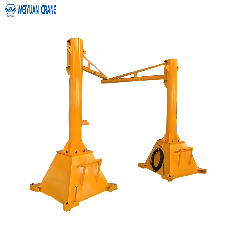
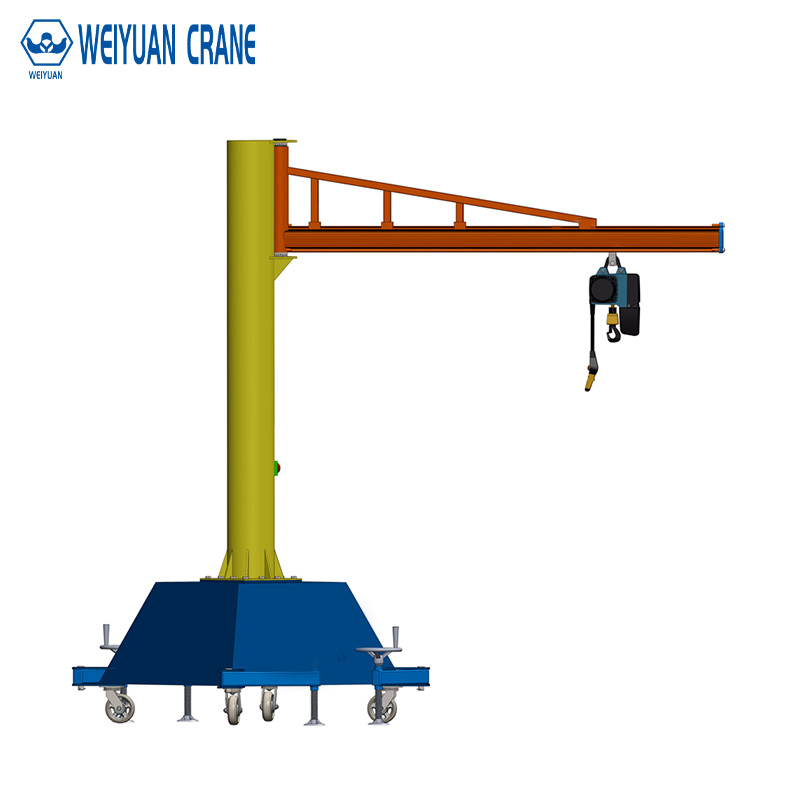
360° — Freestanding Floor-Mounted
A freestanding floor-mounted crane provides full 360° rotation around the mast. The crane covers a complete circle.
Use this for isolated workstations with no wall nearby and coverage needs in all directions. Also appropriate where the crane must serve machines or positions on all four sides of the installation point.
360° rotation requires the largest foundation. It also requires the most floor space around the mast for the operator to safely work without entering the boom sweep zone.
Matching Rotation to Coverage — Not Maximum Rotation
Do not automatically specify 360° because it seems like the most flexible option. A workstation against a wall that only needs 150° of arc coverage is better served by a wall-mounted 180° crane. It costs less. The mounting is simpler. And eliminating the foundation reduces the installation complexity significantly.
Specify the rotation angle based on the workstation analysis result. Not on a default preference.
Part 4: Single Workstation vs Shared Multi-Station Coverage
When Can One Crane Serve Multiple Positions?
A single jib crane can serve multiple workstations — if the station positions fall within the crane’s coverage sector and if the production schedule does not require simultaneous crane use at more than one station.
Conditions for multi-station coverage with a single crane:
All stations are within the boom’s effective working radius.
The rotation arc covers all station positions.
No two stations require crane service at the same time.
Cycle time at each station allows the crane to serve all stations within the production takt time.
Verify the last condition by calculating the crane’s round-trip cycle time and comparing it to the minimum interval between crane demands at each station. If the crane must be at two stations simultaneously, a single crane cannot serve the layout regardless of how well it fits geometrically.
Multi-Station Design Example
A six-station welding line, stations spaced 2.5 meters apart along a straight line. Each station requires one crane lift every 8 minutes. Maximum crane cycle time is approximately 3 minutes including travel, lift, and return. Six stations × one lift per 8 minutes = one lift every 80 seconds on average. The crane can complete a cycle every 3 minutes (180 seconds). The crane can serve all six stations with capacity to spare.
A floor-mounted crane positioned at one end of the line with a 13-meter boom (sufficient to reach all six stations) and 360° rotation can serve this layout. One crane replaces six individual small cranes.
But: if each station requires a crane lift every 3 minutes instead of every 8 minutes, the math changes. Six stations × one lift per 3 minutes = one lift every 30 seconds. The crane cannot keep up. Multiple cranes or a different material handling strategy is required.
Multiple Small Cranes vs One Large Crane — TCO Comparison
Multiple small cranes (one per workstation) provide independent coverage and eliminate scheduling conflicts. Each operator controls their own crane. But each crane requires its own foundation, installation, inspection program, and maintenance budget.
One large crane serving multiple stations reduces capital cost and ongoing inspection/maintenance overhead. It introduces a single point of failure — if the crane is down for maintenance, all served stations stop.
Choose based on: production criticality of the served stations, cycle time analysis results, and the total installed cost comparison including foundations.
Part 5: Hoist Type Selection
The hoist is the component the operator interacts with most. Mismatching the hoist to the workstation creates daily operational friction that persists for the crane’s entire service life.
Manual Chain Hoist
Best for: fewer than 5 to 10 lift cycles per shift, locations without electrical power, and non-time-critical applications.
Not suitable for: any workstation where lifting speed affects production throughput or where operator fatigue from manual pulling is a health and safety concern.
Electric Chain Hoist
The standard choice for most production jib crane applications. Capacities from 1/8 ton (125 kg) to 10 tons. Lift speeds of 2 to 8 m/min depending on capacity.
Select when: lifting frequency is 5 to 30 cycles per shift, capacity is 5 tons or below, and standard positioning accuracy (±50 to ±100mm) is acceptable.
VFD-Controlled Hoist
Adds variable speed control to the electric hoist. The operator can slow to micro-speed (0.2 to 0.5 m/min) for precision placement. Eliminates load swing from abrupt starts and stops.
Select when: precision placement is required (die changes, machine loading with tight tolerances), lifting frequency exceeds 20 to 30 cycles per shift (VFD extends contactor life dramatically at high cycle rates), or load swing must be minimized.
Wireless Remote Control
Allows the operator to control the crane from any position within radio range — not tethered to the pendant cable.
Select when: the operator needs to follow the load to its destination (rather than staying near the crane mount point) or when the pendant cable creates a trip hazard or interference with the production process.
Part 6: Workstation Ergonomics

Getting the crane geometry right is necessary. Getting the ergonomics right makes the crane comfortable to use every day.
Hook Height at the Loading Position
The hook at its lowest position should be at approximately elbow height for the operator when they are standing at the pick-up point. This eliminates bending down to attach the load. It also reduces over-reaching when attaching below-hook hardware.
Standard elbow height: approximately 1,000 to 1,100mm above floor level for an average adult standing operator.
If the lowest hook position is significantly above elbow height, the operator must reach up to attach loads — increasing shoulder fatigue. If it is significantly below, the operator must bend down — increasing back fatigue.
Calculate minimum hook height from the floor: maximum load height + below-hook hardware height + safety margin (100 to 200mm). The hoist must lower the hook to at least this position without contacting the floor or the load it is resting on.
Control Position and Reach
Mount the pendant or position the wireless remote receiver so the operator can control all crane functions without reaching across their body. Pendant cables that hang too short force the operator to walk bent toward the cable origin — a common but easily prevented ergonomic problem.
For pendant-controlled cranes, specify adequate cable length to allow the operator to stand at all required hook positions while holding the pendant comfortably at hip or waist height.
Safety Zone Marking
Mark the crane’s full sweep zone on the floor with yellow and black hazard marking. OSHA 1910.179 requires that the area beneath and around overhead cranes be managed to prevent unauthorized personnel from entering the load swing zone.
For jib cranes in production cells with pedestrian traffic nearby, consider: physical barriers at the arc boundary, warning lights triggered when the crane is in motion, or acoustic warnings when a load is being traveled.
Part 7: Three Workstation Layout Case Studies
Case 1: CNC Turning Cell — Single Station, 1 Ton, 270°
A CNC lathe requires workpiece loading from a pallet beside the machine and unloading to a finished parts cart on the opposite side. The machine is against a wall. The operator works in front of the machine.
Solution: Wall-mounted jib crane on the structural column 1.5 meters from the machine centerline. 1-ton capacity, 4-meter boom. 270° rotation covers both the input pallet position and the finished parts cart position. Electric chain hoist with wireless remote — operator follows the workpiece during loading. Installation eliminates a two-person manual lift operation.
Case 2: Welding Line — Six Stations Shared, 2 Ton, 360°
Six welding stations in a straight line, 2.5 meters apart. Parts weigh 150 to 800 kg. Each station requires one lift every 8 minutes.
Solution: Floor-mounted freestanding crane centered at the end of the line. 2-ton capacity, 12-meter boom, 360° rotation. VFD hoist for smooth control near fixtures. One crane serves all six stations. Foundation at the end of the line does not disrupt material flow between stations.
Case 3: Assembly Cell — Heavy Component Positioning, 5 Ton, VFD
A heavy machinery assembly cell requires positioning gearboxes (800 to 3,500 kg) onto base frames. Tolerance for gearbox mounting hole alignment: ±5mm. Standard across-the-line hoist creates excessive load swing — the load oscillates for 15 to 20 seconds after each motion, increasing cycle time.
Solution: Floor-mounted 5-ton crane, 6-meter boom, 360°. VFD hoist with micro-speed control to 0.2 m/min. Anti-sway algorithm in the VFD drive reduces post-motion swing to under 3 seconds. Load settling time reduction saves approximately 15 minutes of productive time per shift.
Frequently Asked Questions
Q: How do I know if my floor-mounted crane foundation will interfere with underground utilities?
A: Before finalizing the crane mounting location, obtain as-built drawings of all underground services — electrical conduit, compressed air, drainage, and process piping. Mark their routes on the workstation floor plan. Position the crane foundation to avoid crossing any underground service. If a conflict exists, relocate the crane mounting point or engage a civil engineer to design a foundation that bridges the utility without loading it.
Q: Can a jib crane be mounted on a mezzanine or elevated platform?
A: Yes, with structural assessment. The mezzanine or platform structure must be evaluated by a structural engineer for the additional concentrated load from the jib crane foundation. Mezzanine structures are typically designed for uniformly distributed loads — the concentrated foundation point load from a jib crane is a different load type that may require local reinforcement. Do not install a jib crane on any elevated structure without explicit structural engineer approval.
Q: What is the minimum distance between two adjacent jib cranes on the same floor?
A: Adjacent jib cranes must not be able to contact each other during normal operation — their boom sweep zones must not overlap. The minimum center-to-center distance between two 360° cranes equals the sum of their two boom lengths plus a 500mm safety margin. For two 4-meter boom cranes: minimum separation = 4 + 4 + 0.5 = 8.5 meters center-to-center. For cranes with limited rotation arcs where the sweep zones do not overlap at any point, closer spacing may be acceptable — verify by overlaying both sweep sectors on the floor plan.