


How to Install a Jib Crane: 7 Critical Steps from Foundation to First Lift
Introduction
Most jib crane failures trace back to the installation — not the crane itself. Global data consistently shows that 60 to 70% of jib crane incidents result from insufficient installation quality or inadequate maintenance. The crane was specified correctly. The capacity was adequate. The failure happened because the foundation was underprepared, the anchor bolts were under-torqued, or the load test was skipped.
Installation is not complicated. But it is sequential. Each step depends on the previous one being done correctly. Skipping a step — or rushing through it — creates a problem that compounds through every step that follows.
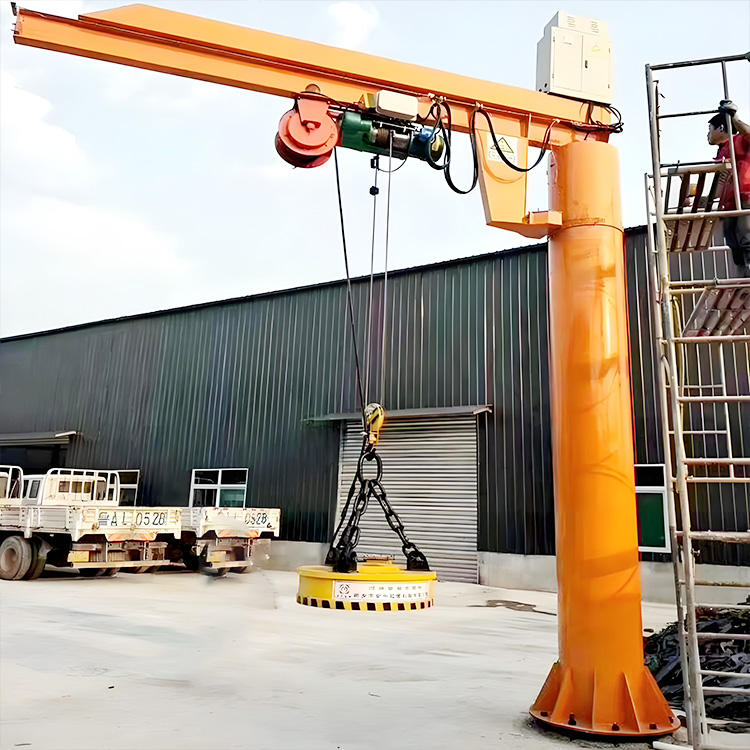
This guide walks through all seven installation steps in order. We cover pre-installation preparation, foundation and anchor bolt work, mast erection and leveling, boom installation, hoist and electrical connection, functional testing, and the load test and documentation that ASME B30.12 requires before first use.
Part 1: Pre-Installation Preparation — Five Things to Confirm Before Work Starts
These five checks take less than a day. Skipping them can cost weeks of rework.
Check 1: Obtain the Manufacturer’s Foundation Load Data Package
The foundation load data package is the engineering document that specifies what the concrete foundation must withstand. It contains: maximum vertical force, maximum overturning moment, maximum horizontal shear force, anchor bolt pattern and embedment depth, and minimum concrete compressive strength.
Do not start any concrete work without this document. Every foundation dimension and reinforcement decision depends on it. Ask for it before placing the purchase order — a supplier who cannot provide foundation load data has not completed the engineering required for a safe installation.
Check 2: Survey Underground Utilities
Mark the proposed foundation location on a floor plan. Request utility drawings from the building owner. Identify all underground services within 2 meters of the proposed excavation: electrical conduit, compressed air lines, drainage, process piping, and structural footings.
A concrete saw that cuts through an electrical conduit delays the project by days. A drill that hits a pressurized air line is a safety incident. Spend 30 minutes on the survey. It is time well spent.
Check 3: Inspect the Concrete Foundation
If the foundation is new: verify that the concrete has reached its design strength before proceeding. The minimum cure period is 28 days for standard concrete at 20°C. At lower temperatures or with accelerated construction schedules, core sample testing confirms strength before the 28-day mark.
If the foundation is existing and being reused: commission a structural engineer to assess it. Verify its original design loads against the new crane’s published foundation loads. Confirm there are no cracks through the anchor bolt zone.
Check foundation surface flatness. The mast base plate must achieve full contact with the concrete. Measure flatness with a precision level. The maximum allowable deviation under the base plate: 2mm over any 300mm length.
Check 4: Prepare Installation Tools and Equipment
Minimum tools required for a standard jib crane installation:
Lifting equipment: a mobile crane, forklift, or chain hoist capable of lifting the heaviest single component with at least 50% capacity margin.
Torque wrench: calibrated, with range covering the anchor bolt torque requirement (typically 300 to 800 N·m for M24 to M36 bolts).
Laser plumb and level: for mast vertical alignment.
Dial indicator with magnetic base: for slewing bearing installation verification.
Multimeter: for electrical circuit continuity and voltage checks.
Calibrated load cell or certified test weights: for the 125% load test.
Check 5: Prepare the LOTO Documentation
Before any work begins on site: prepare the Lockout/Tagout procedure per OSHA 29 CFR 1910.147. Identify all energy sources that must be isolated during installation. Assign a qualified LOTO supervisor. This is not a bureaucratic requirement. It is the procedure that prevents installation personnel from being injured by unexpected energy releases during the work.
Part 2: Step 1 — Foundation and Anchor Bolt Work
Anchor Bolt Installation
For cast-in anchor bolts (embedded during concrete pour): verify that bolt positions match the manufacturer’s base plate drawing within ±3mm in both plan dimensions. Verify bolt projection height above the finished concrete surface matches the specified dimension.
Bolts that are out of position by more than ±3mm cannot be pulled back — the concrete has hardened around them. Correction requires either drilling new holes for chemical anchors or grinding slots in the base plate to accommodate the offset. Both options add cost and delay. Measure bolt positions before the concrete sets.
For post-installed chemical anchors (drilled after concrete is placed): clean each hole thoroughly with compressed air and a wire brush before injecting epoxy. A dusty hole reduces chemical anchor bond strength by 30 to 50%. Follow the adhesive manufacturer’s specified cure time completely before applying any load. At 20°C this is typically 24 to 48 hours. At temperatures below 10°C, cure time extends significantly — confirm the temperature-adjusted cure time from the product data sheet.
Foundation Surface Preparation
The concrete surface under the base plate must be clean and free of laitance (the weak surface layer that forms during concrete curing). Use a wire brush or light grinding to remove laitance before grouting.
Apply non-shrink grout between the base plate and concrete surface after the mast is plumbed and leveled. Grout fills the gap between the base plate and the potentially uneven concrete surface. It provides full bearing contact. Without grout, the base plate rests on high spots — concentrating load on a small area and creating a rocking condition under lateral loading.
Part 3: Step 2 — Mast Installation and Vertical Alignment
Mast Lifting and Initial Placement
Rig the mast for lifting from a point above its center of gravity. A mast lifted below its center of gravity will rotate during the lift — creating an uncontrolled hazard. The correct rigging point is typically at 60 to 65% of mast height from the bottom.
Lower the mast slowly onto the anchor bolts. Thread the nuts hand-tight only. Do not torque until alignment is complete.
Vertical Alignment with Laser Plumb
Mount a laser plumb instrument on a stable surface at least 3 meters from the mast. Project a plumb line onto two faces of the mast at 90 degrees to each other. Measure the deviation at the top of the mast from the plumb line on each face.
Target: mast deviation ≤ 1mm per meter of mast height. For a 4-meter mast: maximum deviation at the top = 4mm.
Adjust vertical alignment using shims under the base plate edges. Add shims to the low side until the laser plumb reading is within tolerance on both faces simultaneously.
Anchor Bolt Torquing
Once the mast is plumb on both faces: torque the anchor bolts to the manufacturer’s specified value using a calibrated torque wrench. Follow a cross-pattern (star pattern) tightening sequence — tighten opposite bolts alternately rather than adjacent bolts in sequence. This ensures even load distribution and prevents the base plate from cocking on the concrete surface.
After initial torquing: re-measure the mast vertical alignment. Heavy torquing can shift the base plate slightly. If the mast has moved outside tolerance, loosen the bolts, re-shim, and re-torque.
Part 4: Step 3 — Boom Installation
Slewing Bearing Installation
For cranes with a slewing bearing (most pillar-mounted jib cranes): the slewing bearing is the pivot between the mast and the boom. Install it according to the manufacturer’s assembly drawing.
Apply anti-seize compound to all slewing bearing mounting bolt threads. Torque the mounting bolts to the manufacturer’s specified value in a star pattern. After initial torquing, re-torque after 24 hours — new bolts take a set under load and lose some of their initial preload.
Verify the bearing axial play after installation. Place a dial indicator on the mast structure with the tip contacting the underside of the bearing’s rotating ring. Push up on the boom tip. The dial reading is the bearing’s axial play. Compare to the manufacturer’s specification — typically 0.1 to 0.3mm for new bearings.
Boom Attachment and Horizontal Level Check
Attach the boom to the slewing bearing. Check boom horizontal level with a precision level on the boom flange at three positions: near the mast, at mid-boom, and at the tip. The boom must be level to within ±2mm per meter of boom length.
A boom that is not level causes the hoist trolley to drift toward the low end under its own weight. This makes precise load placement difficult and creates safety concerns when the operator releases the trolley.
Part 5: Step 4 — Hoist Installation and Electrical Connection
Hoist Trolley Compatibility Check
Before installing the hoist trolley on the boom rail: verify that the trolley wheel width matches the boom’s bottom flange width. The trolley wheels must fully contact the flange — no overhang on either side. A trolley that is too narrow for the flange rides on the flange edges instead of the flange face, creating concentrated contact stress that damages both the wheels and the flange.
Verify the maximum and minimum flange width compatibility from the hoist manufacturer’s dimensional data. This check takes 2 minutes. Missing it produces a crane that damages itself from the first lift.
Wire Rope Reeving
Reeve the wire rope according to the hoist manufacturer’s assembly drawing. The rope must wrap onto the drum in the correct direction. An incorrectly reeved rope wraps across previous wraps rather than in the drum grooves — causing rapid rope wear and potential rope damage.
After reeving, run the hoist through several full hoist cycles with no load. Verify that the rope seats correctly in the drum grooves throughout the full travel range. Look for: rope climbing over previous wraps, rope jumping the drum flange at the end of travel, or irregular rope lay indicating incorrect reeving direction.
Electrical Connection
Connect the hoist power supply per the wiring diagram. Before energizing, verify:
Phase sequence: the hoist motor’s “up” direction must correspond to the pendant “up” button. Connect power, energize briefly, and verify direction with an unloaded test. If the motor runs in the wrong direction, swap any two of the three supply phases at the motor terminal.
Ground continuity: measure resistance from the hook to the building ground. Target: less than 1 ohm. A high-resistance ground path creates a shock hazard.
Emergency stop circuit: verify that pressing the emergency stop button de-energizes all crane motions immediately. The crane must not respond to any control input while the emergency stop is active.
IP seal integrity: inspect all electrical conduit entries and junction box covers. Verify that all cable entry glands are properly tightened and that no conduit entries are open.
Part 6: Step 5 — No-Load Functional Testing
Complete all no-load tests before applying any test weights. Document every result.
Rotation Test
Rotate the boom manually through its full arc in both directions. The rotation resistance should be smooth and consistent throughout the arc. Any stiffness at specific positions indicates: inadequate bearing lubrication, a bearing installation problem, or mechanical interference at that arc position.
For power-assisted rotation: operate the rotation drive through the full arc in both directions. Verify smooth operation and correct direction of rotation relative to pendant button markings.
Hoist Motion Tests
Raise the empty hook from its lowest position to the upper limit switch trip point. The hoist must stop automatically when the upper limit switch activates. The hook block must not contact the hoist body.
Lower the empty hook to the lower limit switch trip point (if fitted). Verify automatic stop before the chain or rope runs out.
Test all speed settings (for two-speed or VFD hoists). Verify that the correct speed responds to each control input.
Brake Test
Raise the empty hook approximately 300mm above the floor. Release the “up” control. Observe for 60 seconds. The hook must not drift downward. Any downward movement — even 1mm — is a brake failure that must be corrected before proceeding.
Part 7: Step 6 — Load Test at 125% Rated Capacity
Why This Test Is Required
ASME B30.12 requires a proof load test at 125% of rated capacity before any new jib crane is placed in service. This test is not optional. It cannot be waived. It verifies that the crane’s structure, hoist mechanism, and foundation can carry loads beyond the rated capacity without failure or excessive deformation.
The test also verifies that all safety devices — limit switches, overload protection, brake — function correctly under load.
Test Procedure
Step 1: Obtain test weights totaling 125% of the crane’s rated capacity. Use certified test weights or loads verified by a calibrated load cell. Do not estimate test weight from visual appearance.
Step 2: Remove all personnel from beneath the crane’s working area. Establish a barrier to prevent anyone from entering during the test.
Step 3: Raise the test load to a height of approximately 300mm above the floor.
Step 4: Travel the crane through its full rotation arc with the load suspended at 300mm height. Verify no abnormal noise, structural movement, or deformation.
Step 5: Raise the test load to the highest practical position (below the upper limit trip point). Hold for 10 minutes. Verify no structural deformation, no brake drift, and no abnormal sounds.
Step 6: Lower the load to the floor. Inspect all structural connections, the foundation, and the anchor bolts for any signs of distress — widened cracks, new cracks, or shifted components.
Acceptance Criteria
The test is passed when: no structural deformation is visible, no anchor bolt movement has occurred, brake hold is verified with zero drift in 10 minutes, all limit switches function correctly under load, and no abnormal noise or vibration was observed during the test.
Part 8: Step 7 — Documentation and Operator Training
Installation Record Package
The completed installation record package must contain:
Foundation load data package from the manufacturer.
Anchor bolt installation records: bolt type, size, embedment depth, torque values applied, and installer name.
Concrete strength verification: either the 28-day test report or the core sample test results.
Mast vertical alignment measurement records.
Boom horizontal alignment measurement records.
Slewing bearing installation records: torque values and axial play measurement.
No-load test results for all motions and safety devices.
Load test records: date, test load source and verification, test procedure followed, pass/fail result, and inspector name and qualifications.
This package is the crane’s permanent maintenance baseline. Retain it for the crane’s full service life.
Capacity Plate and Safety Posting
Mount the crane’s rated capacity plate on the mast at eye level. The plate must show: rated capacity in clearly legible characters, any operational restrictions (boom length limitations, outdoor wind speed limits), and a warning against lifting persons.
Post the emergency procedure at the crane: who to call, how to isolate power, and what to do if the crane becomes unresponsive during a lift.
Operator Qualification
ASME B30.12 requires that jib crane operators be designated as qualified by the employer before operating in production service. Qualified designation requires: training on the specific crane’s controls and rated capacity, demonstrated understanding of the inspection requirements, and awareness of the emergency procedures.
Document the qualification: operator name, crane identifier, training date, trainer name, and the specific topics covered. Retain this record alongside the crane’s installation documentation.
Frequently Asked Questions
Q: Can I skip the 125% load test if the manufacturer tested the crane at the factory?
A: No. ASME B30.12 requires a site load test after installation — not just a factory test. The factory test verifies the crane’s mechanical and structural performance. The site load test verifies the installation — specifically the foundation and anchor bolt system under actual operating loads. A crane with a perfect factory test record can still fail the site load test if the foundation is deficient. Both tests are required.
Q: How long does a typical jib crane installation take?
A: For a standard 1 to 3-tonne floor-mounted pillar jib crane with a new concrete foundation: total elapsed time from foundation pour to completed load test is typically 5 to 7 weeks. This breaks down as: foundation excavation and concrete pour (1 to 2 days), concrete cure period (28 days minimum), mechanical installation (1 to 2 days), electrical connection and no-load testing (half day), and load test (half day). The concrete cure period dominates the schedule. Plan it into the project timeline before ordering the crane.
Q: What happens if the mast vertical alignment is slightly out of tolerance?
A: A mast that is out of vertical tolerance creates asymmetric loading on the slewing bearing. The bearing carries more load on one side of its circumference than the other. Over time, this uneven loading accelerates wear on the overloaded side — reducing bearing life below its design expectancy. It also causes the boom tip to deflect away from level, making precise load placement harder. Correct vertical alignment before the anchor bolts are fully torqued. Correction after full torquing requires partial disassembly.