


Gantry Crane for Infrastructure & Civil Construction: Tunnel, Bridge Beam & Precast Yard Applications
Introduction
Infrastructure construction is one of the fastest-growing drivers of gantry crane demand globally. Governments are investing heavily in roads, railways, bridges, and tunnels. Every major infrastructure project needs cranes. And infrastructure sites create crane requirements that factory cranes cannot meet.
A tunnel boring machine weighs 300 to 800 tonnes. A precast bridge beam weighs 50 to 200 tonnes. A single bridge span may require hundreds of individual lifts over months of construction. These loads, these environments, and these operational patterns demand specifically engineered equipment — not standard industrial gantry cranes pulled from a catalog.
This guide covers the complete specification framework for gantry cranes in civil construction. We explain tunnel crane requirements, bridge construction applications, precast yard layouts, temporary foundation strategies, and the outdoor environment specifications that keep cranes operational on active construction sites.
Part 1: Why Infrastructure Sites Demand Different Crane Specifications
Four Core Differences from Factory Cranes
Factory gantry cranes live in one place. They have permanent foundations, controlled indoor environments, defined production cycles, and predictable loads. Infrastructure cranes have none of these.
Temporary foundations: The crane will be relocated multiple times during the project. Each relocation requires dismantling the track foundation, moving it, and reinstalling it at the new position. Foundation cost and relocation time are direct project costs. They must be minimized.
Frequent repositioning: A bridge beam erection crane moves along the bridge alignment as the structure advances. A tunnel construction crane moves forward as the tunnel boring machine advances. Mobility is not a feature — it is a core operational requirement.
Oversized and irregular loads: Precast concrete segments, steel bridge girders, tunnel boring machine components, and prefabricated structural sections are the loads these cranes handle. They are heavy, long, and awkward. Standard crane hook configurations cannot handle them without specialized below-hook lifting devices.
Unpredictable site conditions: Open construction sites experience wind, rain, temperature extremes, and rough ground conditions that factory cranes never see. IP66 electrical protection, wind-rated structural designs, and robust mechanical systems are mandatory — not optional upgrades.
Typical Load Ranges in Civil Construction
Understanding the weight ranges involved helps explain why standard catalog cranes are usually inadequate:
Precast tunnel segments: 5 to 20 tonnes each. Hundreds of identical segments per tunnel kilometer. High cycle frequency, repetitive handling, precision placement.
Precast bridge beams (standard highway): 50 to 200 tonnes per beam. Long, slender, sensitive to bending during lifting. Require multi-point lifting beams.
Steel bridge girder sections: 20 to 150 tonnes. Complex geometry. Require precise positioning at the splice connections.
Tunnel boring machine (TBM) components: 50 to 500 tonnes per major component assembly. Extremely heavy. Handled only a few times — at launch and at retrieval.
Precast culverts and retaining wall sections: 5 to 40 tonnes. High volume, repetitive handling.
Part 2: Tunnel Construction Gantry Cranes
TBM Assembly and Retrieval
A modern TBM for a major urban transit tunnel is one of the largest pieces of machinery in civil construction. The main bearing alone can weigh 50 to 80 tonnes. The complete TBM cutterhead assembly often exceeds 200 tonnes. Assembling this machine at the launch shaft — and later retrieving it at the reception shaft — requires cranes that match these extraordinary capacities.
TBM assembly cranes typically range from 100 to 800 tonnes rated capacity. They are almost always custom-engineered for the specific TBM dimensions and shaft geometry. The crane must fit within the shaft dimensions while providing adequate hook height above the assembly platform.
Standard configuration for TBM assembly: double-girder gantry crane with twin hoisting mechanisms operating in tandem. The twin hoisting configuration allows asymmetric loads (individual TBM components with off-center centers of gravity) to be handled with controlled orientation. Each hoist is independently controllable for fine positioning during assembly.
Precast Tunnel Segment Handling
Segmental lining is the standard construction method for bored tunnels worldwide. Precast concrete segments are manufactured at a casting yard, transported to the tunnel portal, and fed into the tunnel via a segment logistics system.
Each segment weighs 5 to 15 tonnes depending on the tunnel diameter and lining design. Handling accuracy is important — segments that are damaged during handling must be replaced, adding direct cost and program delay.
Gantry cranes in segment casting yards serve three functions:
Moving green segments from casting molds to initial curing positions.
Moving cured segments from the curing area to the stockpile.
Loading segments onto segment delivery vehicles for transport to the tunnel portal.
The crane’s lifting attachment for tunnel segments is typically a purpose-designed spreader frame with vacuum cups or mechanical clamping pads. These distribute the lifting force over the segment’s surface without creating the concentrated point loads that would crack the concrete.
Underground and Low-Headroom Applications
Tunnels do not have unlimited headroom. Cranes operating inside a tunnel entry structure, above a shaft, or within a cut-and-cover tunnel section must fit within defined clearance envelopes. Low-headroom hoist designs — European-type hoists with compact body dimensions — are frequently specified for these applications.
Electrical systems for tunnel cranes require IP67 or higher enclosure protection. Groundwater ingress and high humidity are standard tunnel conditions. Standard IP54 equipment fails rapidly in these environments.
Part 3: Bridge Construction Gantry Cranes
Precast Beam Yard Cranes
Every major precast bridge beam production facility needs gantry cranes. The yard produces beams, stores them until they are needed on site, and loads them onto transport vehicles for delivery.
A typical precast beam yard layout has three zones:
Production zone: where the casting beds are located. The crane here serves the formwork, places rebar, and moves beams from the casting beds to the curing area. Cycle frequency is moderate — one or two beams per bed per day.
Storage zone: where cured beams await transport. The crane stacks beams in the storage area, sometimes two or three layers high. The crane must handle the beam’s full weight plus the weight of beams already stacked on the storage pallet or blocking.
Loading zone: where beams are transferred to transport vehicles. Precision positioning is critical. The beam must be accurately placed on the transport vehicle’s bolsters or saddles. A beam dropped or misplaced at this stage requires recovering a heavy, awkward load from an unstable position.
The gantry crane serving all three zones typically spans the full yard width — often 20 to 40 metres — with a runway length matching the yard’s production and storage extent.
Bridge Beam Erection Cranes
Erecting precast beams onto bridge piers is among the most technically demanding crane operations in civil construction. The crane must:
Span from one completed span to the next ahead of the advancing construction.
Lift beams from the transport vehicle at the rear of the structure.
Travel the beam along the bridge to the erection position.
Lower the beam precisely onto the pier caps with sub-50mm positioning accuracy.
Two equipment types handle bridge beam erection:
Rubber-tired gantry crane (RTG): A wheeled crane that travels along the ground beside or below the bridge structure. The RTG can reposition itself between spans without the bridge structure being load-bearing. Its limitation: it needs adequate ground clearance and load-bearing ground beneath it.
Launching gantry (also called a bridge erection machine): A self-launching structural gantry that spans from pier to pier and advances itself along the bridge. It is supported entirely by the completed piers — not by the ground below. Launching gantries are the standard solution for elevated viaducts where the crane cannot access the ground below the structure.
Double Crane Lifts for Long Girders
Precast beams for major highway bridges can be 35 to 50 metres long and weigh 100 to 200 tonnes. No single lifting point serves a beam of this length — the bending moment from an off-center pick would crack the concrete.
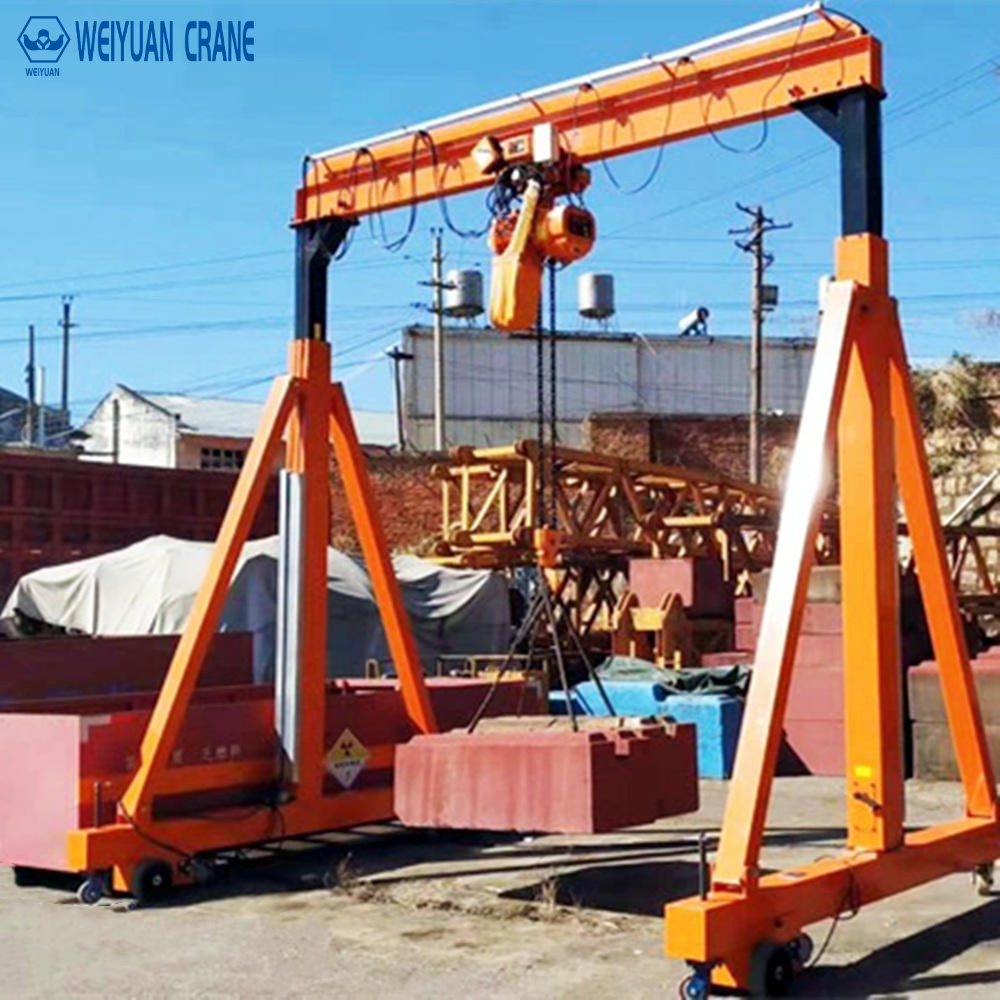
Long beam erection uses two cranes in tandem — either two independent gantry cranes or a single gantry crane with two independent hoisting mechanisms. The two pick-up points are positioned at the beam’s quarter-points (25% and 75% of the beam length from each end). This two-point lifting arrangement minimizes the bending moment in the beam during lifting.
Synchronized tandem lifting requires both hoists to travel at precisely the same speed. Any differential speed creates a tilting condition that converts vertical load into bending moment. Synchronization control — automatic load-equalizing electronic control — is standard for tandem beam lifts above 80 tonnes.
Part 4: Precast Concrete Component Facilities
Three-Zone Yard Layout Planning
An efficiently planned precast yard uses the crane’s travel length productively. The three-zone layout positions activities in sequence along the crane runway:
Zone 1 (Production): casting beds, formwork storage, rebar prefabrication. The crane primarily handles formwork components and individual rebar cages. Load weights: 1 to 20 tonnes.
Zone 2 (Curing and Intermediate Storage): green element storage area and initial curing area. The crane moves elements from Zone 1 after stripping. Moderate cycle frequency. Load weights match the finished element weight.
Zone 3 (Finished Goods Storage and Dispatch): stockpile of completed, accepted elements. The crane stacks elements and loads vehicles. Highest precision requirement of the three zones.
The crane runway length must cover all three zones with adequate end-of-runway clearance at both ends. The typical minimum end clearance: 2 metres beyond the last production or storage position at each end.
Two-Crane Tandem Operations
Large precast yards sometimes operate two gantry cranes on the same runway simultaneously. This increases throughput. It also introduces collision risk.
Anti-collision provisions for two cranes on shared runway:
Minimum operating separation: 3 metres between crane structures at all times. This is enforced by end stops and travel limit switches on both cranes — not by operator awareness alone.
Electronic anti-collision: radar or laser distance sensors that detect the approaching second crane and trigger automatic travel slowdown and stop before the minimum separation is reached.
Operational zones: the runway is divided into a production zone (Crane 1’s primary operating area) and a loading zone (Crane 2’s primary area) by physical or electronic boundaries. The cranes can enter each other’s zones only when the other crane is confirmed stationary.
Part 5: Temporary Foundations and Relocatable Design
Track Foundation Options for Construction Sites
Permanent embedded crane rail foundations — the standard for factory installations — are impractical for construction sites. The foundation cost would exceed the crane’s value if it had to be rebuilt at each new position.
Three temporary foundation approaches are used in practice:
Precast concrete sleepers: Short precast concrete blocks placed on compacted ground, with the rail fastened to them. Can be repositioned with a small excavator or forklift. Adequate for lighter cranes (up to approximately 30 to 50 tonnes) on reasonably firm ground.
Steel railway-type sleepers: Standard or purpose-made steel sleepers with clip-fastened rails. More durable than precast concrete for high-cycle site conditions. Repositionable without special equipment.
Continuous concrete strip with pre-drilled rail anchor slots: A strip of concrete — 200 to 300mm thick, 600 to 800mm wide — poured along the crane rail alignment with pre-positioned anchor bolt holes. More expensive to install than sleepers but provides better load distribution on soft ground and higher rail alignment precision.
Rubber-Tired Cranes — Maximum Mobility
For applications where even temporary track foundation cost and relocation time are unacceptable, rubber-tired gantry cranes (RTG) provide the maximum mobility. They travel on pneumatic tires without track.
RTG advantages for construction sites:
No foundation required. The crane travels to its new position under its own power.
Can work in multiple areas of a large site without dismantling.
Can cross roadways and other infrastructure without requiring special provisions.
RTG limitations:
Maximum capacity typically 200 to 300 tonnes for standard construction RTGs.
Requires adequately load-bearing ground beneath the tire path.
Less stable than rail-mounted cranes under eccentric loads at maximum radius.
Part 6: Outdoor Environmental Specifications
Wind Load Design
Open construction sites are exposed to unobstructed wind flow. A crane near a completed bridge deck is in the wake of the structure — wind turbulence amplifies the dynamic loads on the crane. A crane at a coastal reclamation site or on an elevated bridge is in full exposure.
ASCE 7-22 (USA) and EN 1991-1-4 (Europe) provide the design wind speed maps for crane structure design. For most construction crane applications:
Operating wind design speed: 12 to 20 m/s (crane must maintain safe operation up to this wind speed).
Non-operating storm wind design speed: 40 to 55 m/s (crane must survive this wind speed when secured in its storm position).
The non-operating storm design is often the governing structural load case for large outdoor gantry cranes. The crane structure must resist the full storm wind force without tipping or structural failure — even when unloaded and in its parked position.
Travel Speed Limits and Stop Procedures
When wind speed exceeds the operating limit:
Step 1: Immediately lower any suspended load to the ground.
Step 2: Travel the crane to the designated parking position.
Step 3: Engage rail clamps on all four wheels.
Step 4: Engage storm anchor devices if provided.
Step 5: Lower the hook to the bottom position and secure the rope.
Step 6: Isolate electrical power to the crane.
Step 7: Document the action in the crane’s operating log.
Wind speed monitoring: install a calibrated anemometer at the crane’s highest point. The anemometer feeds a display at the operator’s station and triggers an alarm at the operating wind speed limit. Do not rely on site weather forecasts — local conditions at crane height can differ significantly from ground-level measurements.
Electrical Protection for Site Conditions
Construction sites subject cranes to water, mud, dust, and cleaning operations that factory environments do not. All electrical components on construction gantry cranes require:
IP65 minimum for enclosed electrical cabinets away from direct water exposure.
IP66 for any enclosure subject to direct rain or hosing-down cleaning.
IP67 for components in the splash zone of concrete casting operations or water-curing areas.
Corrosion protection: stainless steel or hot-dip galvanized hardware for all outdoor fasteners. Standard zinc-electroplated hardware corrodes through in 12 to 18 months on active construction sites.
Frequently Asked Questions
Q: Can a standard factory gantry crane be used on a construction site if the capacity is adequate?
A: Not without significant modification. Standard factory cranes are not designed for outdoor wind loads, temporary foundations, or the relocation operations that construction sites require. The structural design, electrical protection, foundation system, and relocation provisions are all different. Using a factory crane on an outdoor construction site without engineering assessment of outdoor wind loads and temporary foundation adequacy creates both a safety risk and a premature failure risk.
Q: How many times can a construction gantry crane be relocated during its service life?
A: A well-designed construction gantry crane can be relocated 5 to 15 times over its service life without structural degradation — provided the relocation is done correctly (controlled disassembly, no dropped connections, correct torquing of all bolted joints at reassembly) and the crane is inspected after each relocation. Each relocation should be treated as a new installation, including a post-reassembly load test at reduced load (typically 110% of rated capacity).
Q: What is the difference between a launching gantry and a standard bridge construction gantry crane?
A: A launching gantry is a purpose-designed self-propelled erection machine that spans between bridge piers and uses the completed bridge structure as its support. A standard bridge construction gantry crane is a conventional gantry supported by ground-level rails running parallel to the bridge. The launching gantry is used where ground access is impossible — on elevated viaducts, over water, in mountainous terrain. The standard ground-supported gantry is used where adequate ground-level access exists alongside the bridge.