


How to Select a Gantry Crane Span, Leg Height & Runway Length: 5 Critical Sizing Decisions
Introduction
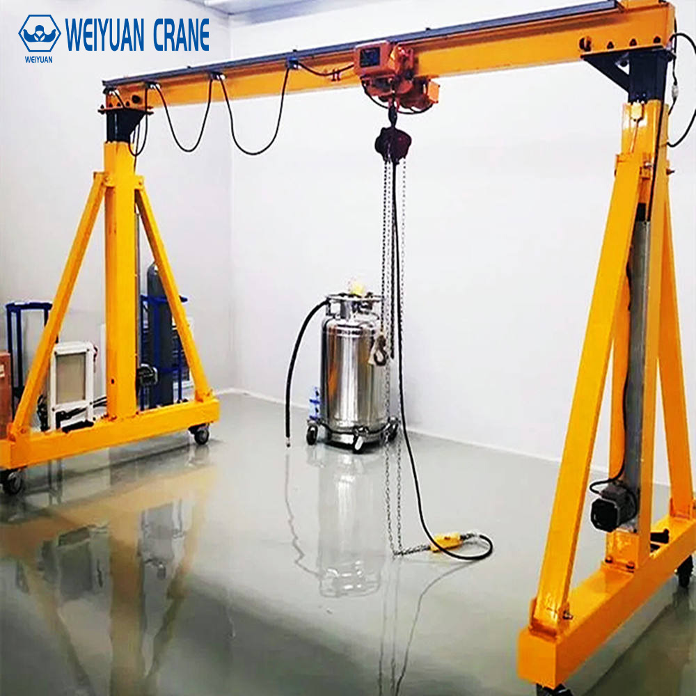
Capacity errors are expensive. Span errors are worse. A crane with the wrong capacity can be replaced when the application changes. A crane with the wrong span cannot serve the workstation it was installed to cover — regardless of its capacity, duty class, or control system.
Most buyers focus on capacity first. They should focus on geometry first. The five dimensional parameters — span, leg height, wheel base, runway length, and cantilever — determine whether the crane physically fits the application. Capacity determines whether it can lift the loads within that geometry.
Get the geometry wrong and you discover the problem after installation. Correcting it means modifying the crane structure (expensive) or replacing it entirely (more expensive). This guide provides the complete framework for getting all five sizing decisions right before the purchase order is placed.
Part 1: Why All Five Parameters Must Be Decided Together
The five dimensional parameters are interdependent. Changing one affects the others. They cannot be decided sequentially — they must be evaluated as a system.
Span drives structural weight. Every additional metre of span increases the bridge girder’s bending moment, requiring a deeper and heavier section. A 20-metre span bridge girder for a 10-tonne crane weighs roughly twice as much as the same crane’s 10-metre span bridge. This weight increase affects the runway rail size, the runway beam design, and the foundation loads.
Leg height drives stability requirements. Tall legs create a high center of gravity. The crane structure must resist tipping under the combination of lateral wind load and eccentric vertical load. The taller the legs, the wider the wheel base (or the heavier the structural bracing) required to maintain stability.
Runway length determines productive coverage. A short runway that does not reach all required work positions wastes the investment in the crane. A runway that is much longer than necessary creates unnecessary foundation cost.
Cantilever affects rated capacity. A gantry crane’s rated capacity applies at the hook position directly above the runway rails. When the trolley moves to the cantilever zone (beyond the supporting leg), the overturning moment on the crane structure increases. The rated capacity in the cantilever zone is typically 20 to 30% less than the rated capacity over the main span.
Design the geometry around the application. Then select the crane parameters to match the geometry. Never select parameters from a catalog and hope the geometry works out.
Part 2: Decision 1 — Span
Definition
Span is the horizontal distance between the centerlines of the two runway rails. It defines the maximum width of the working area directly below the crane.
How to Determine the Required Span
Step 1: Draw the workstation or work area to scale on a floor plan.
Step 2: Mark the outermost positions that the crane hook must reach. These are the edges of the required coverage area.
Step 3: Measure the total width of the required coverage area.
Step 4: Add the minimum clearances. The crane’s legs will be positioned outside the coverage area. Add at least 500mm per side between the outermost required hook position and the crane leg centerline. This clearance allows the hoist trolley to reach the edge positions without the trolley bumper contacting the leg structure.
Required span = Coverage width + (2 × 500mm minimum clearance) = Coverage width + 1,000mm minimum.
For a coverage width of 10 metres: minimum span = 11 metres. Select 12 metres from the standard series.
Step 5: Check for leg interference. The crane legs must not obstruct any work activity, personnel pathway, or vehicle route within the working area. If legs at the calculated span position would create an obstruction, increase the span.
Standard Span Series
Standard gantry crane spans (in metres):
4 — 5 — 6 — 7.5 — 9 — 10.5 — 12 — 16 — 18 — 20 — 22 — 25 — 28 — 30 — 32 — 35
Select the first standard span that exceeds the calculated minimum. Do not select the span that exactly equals the calculated minimum — always have coverage margin.
Span and Structural Weight
For planning purposes: gantry crane bridge girder weight increases approximately 20 to 30% for each 20% increase in span at the same rated capacity. This weight increase directly affects:
Runway rail section size (heavier bridge = higher wheel loads = larger rail).
Runway beam structural requirements (higher wheel loads require stronger runway beams).
Foundation loads (higher wheel loads require larger foundations).
Specifying excessive span to “have more room” has real structural and cost consequences. Match the span to the actual coverage requirement.
Part 3: Decision 2 — Leg Height
Definition
Leg height is the vertical distance from the top of the runway rail to the ground level beneath the crane. It determines the maximum hook height available within the crane’s design.
Hook Height Calculation
The usable hook height — the distance from the floor to the hook at its highest raised position — is always less than the leg height. The difference equals the hoist’s minimum headroom dimension.
Usable hook height = Leg height − Hoist minimum headroom
Minimum headroom is the distance from the bottom of the crane girder to the hook at its highest position. For standard chain hoists: 300 to 600mm. For European-design low-headroom hoists: 200 to 400mm. For wire rope hoists with large drums: 500 to 1,000mm.
Required leg height = Required hook height + Hoist minimum headroom
Calculate required hook height by adding:
Component 1: Maximum height of the tallest object the crane must lift over. This is the height above floor level of the highest obstruction the load must clear during horizontal travel.
Component 2: Clearance above the obstruction during travel. Minimum 300mm. Recommended 500mm for reliable operation.
Component 3: Height of the load itself (from floor to top of load at its tallest orientation during travel).
Component 4: Rigging and below-hook hardware height. The distance from the top of the load to the hook.
Required hook height = Component 1 + Component 2 + Component 3 + Component 4.
Leg Height and Structural Stability
Tall legs reduce the crane’s resistance to tipping under lateral loads. The stability criterion: the crane must not tip when subjected to the maximum rated load at maximum offset from the crane centerline plus the design lateral wind load.
As a practical guideline: leg height should generally not exceed 60 to 70% of the span for standard industrial gantry cranes without additional stability analysis. A 10-metre span crane with legs taller than 6 to 7 metres requires specific stability calculation by the crane manufacturer.
If the required leg height exceeds this guideline ratio, consider: increasing the span (wider base improves stability), adding lateral bracing to the leg structure, or increasing the wheel base (distance between front and rear wheels on each side).
Unequal Leg Heights
Some applications require the two crane legs to be at different heights. A crane spanning from a loading dock (elevated) to the floor level beside it must accommodate the elevation difference between the two runway levels. This unequal-leg design creates an asymmetric bridge structure with different end reactions at each support.
Unequal leg cranes require specific structural engineering. The standard symmetric crane calculations do not apply. Always engage the crane manufacturer’s engineering team for unequal-leg configurations.
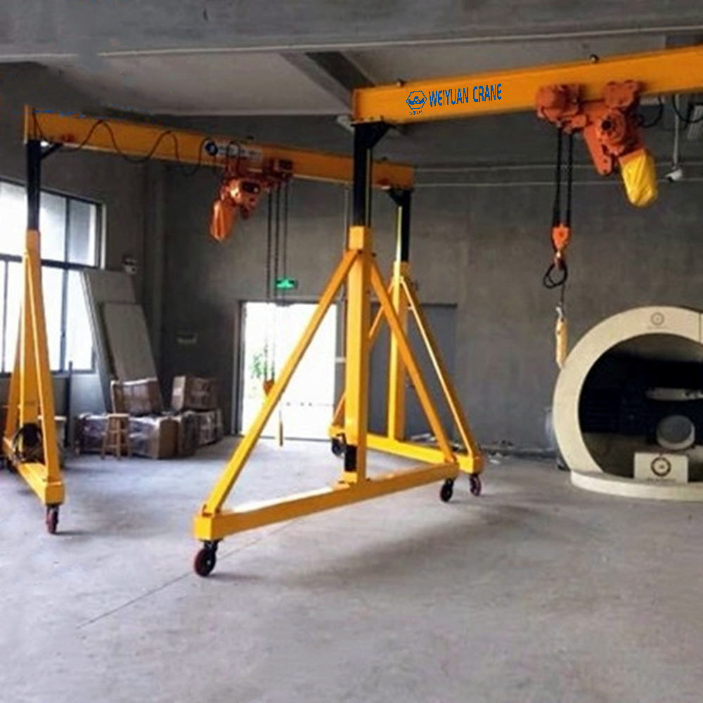
Part 4: Decision 3 — Wheel Base (Leg Spacing)
Definition
Wheel base (also called leg spacing or outrigger spacing) is the distance between the front and rear wheels on the same side of the crane. It is measured parallel to the runway direction.
Why Wheel Base Matters
The wheel base determines the crane’s resistance to tipping in the runway direction. When the crane travels and stops suddenly, the inertia force acts at the crane’s center of gravity — which is above the runway rail. This forward or rearward tipping tendency is resisted by the wheel base.
A longer wheel base provides more stable operation during travel and braking. It also distributes the crane’s weight over a longer section of runway, reducing the maximum wheel load at any single rail point.
Typical Wheel Base to Span Ratios
For standard industrial gantry cranes: wheel base is typically 20 to 35% of span.
10-metre span crane: typical wheel base 2.0 to 3.5 metres.
20-metre span crane: typical wheel base 4.0 to 7.0 metres.
30-metre span crane: typical wheel base 6.0 to 10.5 metres.
For cranes with unusually tall legs or operating at high travel speeds: use the larger end of the wheel base range.
Part 5: Decision 4 — Runway Length
Definition
Runway length is the distance between the physical end stops at each end of the crane’s travel path. It determines how far the crane can travel along the work area.
Calculating Required Runway Length
The required runway length is not simply the length of the work area. It must include end-of-travel buffer zones at both ends.
End buffer zone: the distance from the end stop to the nearest work position the crane must reach. This buffer must accommodate: the deceleration distance from full travel speed to stop, the overtravel distance before the end stop engages (typically 100 to 300mm for cushioned end stops), and a safety margin.
Minimum end buffer: 500mm for cranes with VFD-controlled smooth stopping. 1,000mm for cranes with contactor (across-the-line) travel motors that stop more abruptly.
Required runway length = Work area length + (2 × end buffer distance).
For a 25-metre work area with VFD travel control: required runway length = 25 + (2 × 0.5) = 26 metres minimum. Select 27 or 28 metres to provide working margin.
Runway Length and Foundation Cost
Each additional metre of runway requires approximately 2 metres of additional rail foundation (one metre per rail, both sides). For a standard outdoor gantry crane on a continuous concrete rail pad: foundation cost is approximately $150 to $400 per runway metre (both rails combined) depending on soil conditions and foundation depth.
Runway length has a direct, linear relationship with foundation cost. Avoid specifying excess runway length. Match it precisely to the work area plus the required buffer distances.
Multi-Crane Shared Runways
When two cranes operate on the same runway: the runway length must accommodate both cranes simultaneously, including the minimum safe separation between them.
Minimum separation between cranes on shared runway: 3 metres between the closest structural points of the two cranes during simultaneous operation. Both cranes’ structural widths (wheel base plus overhang) must be added to the required separation.
Total runway length for two cranes = Crane 1 structural length + Minimum separation + Crane 2 structural length + Work area length + End buffers.
Part 6: Decision 5 — Cantilever Length
Definition
Cantilever (also called overhang) is the portion of the bridge girder that extends beyond the supporting leg on either side. If the bridge girder ends exactly at the leg centerlines, there is no cantilever. Most gantry cranes have no cantilever. Some applications specifically require cantilever to reach positions that a non-cantilevered bridge cannot cover.
When Cantilever Is Needed
Cantilever is specified for two situations:
Loading dock access: the crane must reach over the edge of a loading dock to access vehicles parked alongside. A cantilever of 1 to 3 metres allows the hook to position over the truck bed while the crane legs remain on the dock surface.
Edge-of-area coverage: the required coverage area extends slightly beyond where the crane leg can practically be positioned. A short cantilever closes this gap without requiring the span to be increased by 3 to 4 metres.
Cantilever and Rated Capacity
The rated capacity of a gantry crane is specified at the hook position over the main span between the legs. When the trolley moves into the cantilever zone, the overturning moment increases. The permissible load in the cantilever zone is reduced accordingly.
Typical cantilever capacity reduction:
Cantilever ≤ 10% of span: capacity reduction approximately 10 to 15%
Cantilever 10 to 20% of span: capacity reduction approximately 20 to 30%
Cantilever > 20% of span: capacity reduction 30% or more — specific engineering calculation required
Always specify the cantilever zone rated capacity separately when requesting quotes. Do not assume the full span rated capacity applies in the cantilever zone.
Part 7: Two Worked Sizing Examples
Example A: Precast Beam Yard Crane
Application: a precast concrete yard producing highway bridge beams. The yard is 18 metres wide (casting beds and storage combined). The longest beam is 35 metres. Maximum beam weight is 120 tonnes.
Span: coverage width 18 metres + 2 × 600mm clearance = 19.2 metres. Select 20-metre standard span.
Leg height: beams are stored on blocking 600mm above the ground. The tallest stacked beam height (2-layer storage) is 3.2 metres. Hook travel clearance above top beam: 500mm. Rigging spreader beam depth: 800mm. Required hook height = 3.2 + 0.5 + 0.8 = 4.5 metres. Plus hoist headroom 700mm. Required leg height = 4.5 + 0.7 = 5.2 metres. Select 5.5 metres.
Runway length: production zone 80 metres + storage zone 120 metres + loading zone 40 metres = 240 metres total work area. Plus 2 × 1.0 metre end buffer = 242 metres. Select 245-metre runway.
Capacity: 120 tonnes maximum beam weight + 3-tonne spreader beam + 1-tonne rigging × 1.15 dynamic factor = 141 tonnes. Rounded up: select 160-tonne rated capacity.
Example B: Manufacturing Workshop Crane
Application: outdoor steel fabrication yard, 15 metres wide. Maximum fabricated section weight: 25 tonnes. Storage racks 2.5 metres high. Vehicle access on both sides of the yard.
Span: coverage width 15 metres + 2 × 500mm = 16 metres. Select 16-metre standard span.
Leg height: 2.5m storage height + 400mm clearance + 800mm rigging = 3.7m hook height. Plus 600mm hoist headroom = 4.3m. Select 4.5-metre leg height.
Runway length: 60-metre fabrication area + 2 × 0.5-metre buffers = 61 metres. Select 63-metre runway.
Capacity: 25-tonne load + 1-tonne rigging × 1.15 = 29.9 tonnes. Select 32-tonne rated capacity.
Frequently Asked Questions
Q: Can I increase the span after the crane is installed if I need more coverage?
A: Span increase after installation is possible but expensive. It requires: replacing the bridge girder with a longer one, modifying or repositioning the leg structures, relocating the runway rails further apart, modifying or replacing the runway foundations, and recertifying the modified crane with a new load test. The cost typically exceeds 60 to 80% of a new crane’s purchase price. Specify adequate span at procurement — it is far cheaper than post-installation modification.
Q: What is the maximum span for a single-girder gantry crane?
A: Single-girder gantry cranes are practical to approximately 20 to 25 metres span at capacities up to 16 to 20 tonnes, subject to the deflection limit of L/600 under rated load. Above 20 metres span or above 20-tonne capacity, double-girder construction is typically required to meet deflection limits without an excessively deep and heavy girder section.
Q: How do I account for future expansion in runway length?
A: Design the runway foundation with a defined extension direction and adequate foundation strength at the current end stops. When extension is needed, the end stop is moved, additional rail sections and sleepers are added, and the foundation is extended. Planning for future extension adds minimal cost at installation — typically an additional $1,000 to $3,000 for the foundation design provisions and extra rail anchor provisions at the current end stop location.