


Electric Hoist Trolley Types Guide: Push, Motorized & Geared — Which Suits Your Application?
Introduction
The trolley is the component that moves the hoist horizontally. Most buyers choose their hoist carefully and then select the trolley as an afterthought — often just selecting whatever is cheapest or whatever the hoist supplier recommends by default.
This is a mistake. The wrong trolley type makes the crane harder to use, wears out faster, or creates ergonomic problems that operators complain about for the next 15 years.
A push trolley in an application that needs motorized travel turns the operator into a pushing machine for every cycle. A motorized trolley in an application where the operator needs to follow the load creates pendant cable management problems. A geared trolley specified too light wears out its wheels in 2 years instead of 10.
This guide explains the four main trolley types, their specific applications, and how to select the correct one for your application.
Part 1: What a Hoist Trolley Does
A hoist trolley has one function: to carry the hoist horizontally along the beam or crane runway as the operator moves the load from the pickup position to the deposit position.
The trolley sits on the lower flange of the beam. Its wheels run on the beam’s bottom flange surface. The hoist hangs below the trolley. Together, the trolley and hoist create the complete horizontal-plus-vertical material handling system.
The trolley must:
Support the full weight of the hoist plus the rated load — with the dynamic amplification factor applied.
Run smoothly on the beam flange profile — wheel tread width must match the flange width.
Maintain a defined clearance between the wheel flanges and the beam web — too tight and the trolley binds; too loose and it derails.
Travel the full beam length without jamming at rail joints or at the end stops.
Every trolley has a rated capacity — the maximum load it can carry, including the hoist weight. A 1-tonne trolley used with a 1-tonne hoist is already at full capacity before any load is lifted. The trolley capacity must be: (hoist weight + rated load) with margin.
Part 2: Trolley Type 1 — Push Trolley (Manual Travel)
How It Works
A push trolley has no drive mechanism. The operator pushes the hoist and load horizontally along the beam by hand. The operator walks alongside the load, guiding it to the destination.
Push trolleys use either: plain bearing wheels (simple, lowest cost, adequate for low frequency), or sealed ball bearing wheels (lower rolling resistance, longer life, recommended for regular production use).
When Push Trolleys Are Correct
Low cycle frequency: fewer than 10 to 15 complete travel cycles per shift. The operator pushes the load occasionally — not continuously throughout the shift.
Short travel distances: below 8 to 10 metres. Pushing a load over longer distances creates operator fatigue. Beyond 10 metres with any significant load, motorized travel becomes a safety and ergonomic necessity.
Light to medium loads: up to approximately 2 to 3 tonnes. Above this weight, the rolling resistance of the trolley under full load becomes significant. The operator must apply substantial force to start and stop the load.
Applications where the operator needs to walk with the load: if the operator must guide the load into a precise position while following it, the push trolley allows this naturally. The operator is in direct physical contact with the trolley — they feel the load’s movement and can make micro-corrections continuously.
Limitations of Push Trolleys
Ergonomic loading on the operator: at high cycle rates or long distances, pushing becomes physically demanding. OSHA’s ergonomic guidelines identify sustained pushing force above 50 N (approximately 5 kg effort) as a potential musculoskeletal risk factor. On a loaded push trolley, the required push force is proportional to the load weight and the bearing condition.
No speed control: the operator determines the travel speed. This creates load swing when the operator accelerates or decelerates suddenly.
Not compatible with automation: push trolleys cannot be incorporated into automated or semi-automated material flow systems.
2026 Price Reference (Push Trolley Only)
Capacity 250 kg to 1 tonne: $150 to $450
Capacity 1 tonne to 3 tonnes: $300 to $750
Capacity 3 tonnes to 5 tonnes: $550 to $1,200
Part 3: Trolley Type 2 — Geared (Hand Chain) Trolley
How It Works
A geared trolley uses a hand chain pulled by the operator to drive the trolley along the beam. The hand chain connects to a pinion gear that engages with a rack on the trolley’s drive wheel — or directly drives the trolley wheel through a gear reduction.
The mechanical advantage of the gear reduction makes it possible for an operator to move heavier loads than a push trolley allows, with less physical effort. The trolley speed is low — typically 5 to 15 m/min depending on the gear ratio and operator pull speed.
When Geared Trolleys Are Correct
Moderate loads where push force becomes difficult: 2 to 10 tonnes. The gear reduction allows an operator to move a 5-tonne load with a manageable hand chain pull force of 150 to 300 N.
No electrical power available: the geared trolley requires no electricity. It is purely mechanical. This makes it suitable for: outdoor locations without power infrastructure, temporary installations, and areas where electrical equipment is restricted.
Low cycle frequency: geared trolleys are operated at human pace. They are suitable for up to 15 to 20 travel cycles per shift in normal service.
Limitations of Geared Trolleys
Speed: geared trolleys are slow — 5 to 15 m/min maximum. For applications where cycle time is a production constraint, geared trolleys are inadequate.
Operator engagement: the operator must stand at the trolley and pull the hand chain continuously throughout the travel. Unlike a motorized trolley where the operator presses a button and waits, the geared trolley requires continuous physical effort.
2026 Price Reference (Geared Trolley Only)
Capacity 1 to 3 tonnes: $400 to $900
Capacity 3 to 5 tonnes: $700 to $1,500
Capacity 5 to 10 tonnes: $1,200 to $2,800
Part 4: Trolley Type 3 — Motorized Trolley (Electric Travel)
How It Works
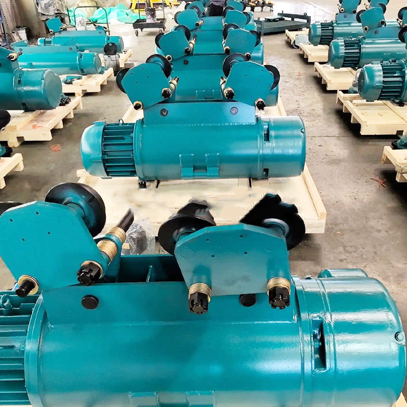
A motorized trolley has an electric drive motor that powers the trolley’s travel wheels. The operator controls travel direction and speed from the hoist pendant control. The drive motor accelerates the trolley to operating speed and decelerates it to a stop at the destination.
Two control types are standard:
Contactor-controlled (on/off): the motor runs at full speed or is off. No intermediate speed. The operator makes the load travel at full speed and stops it when the hook is approximately above the target position. Load swing from the abrupt stop must be damped by the operator.
VFD-controlled (variable speed): the motor accelerates gradually and decelerates gradually. Load swing is minimized because there is no abrupt start or stop. The operator can also use slow speed for final positioning — useful for precision placement applications.
When Motorized Trolleys Are Correct
High cycle frequency: above 15 travel cycles per shift. The motorized trolley eliminates operator physical effort for horizontal travel — the operator presses a button and the trolley moves.
Long travel distances: above 10 metres. Motorized travel covers long distances consistently without operator fatigue.
Any capacity where pushing would create ergonomic risk: for loads above 2 to 3 tonnes on any beam length, motorized travel should be the default specification.
Applications where the operator should stay stationary: assembly lines where the operator works at a fixed position and the crane delivers components to the workstation. The operator does not walk with the load.
Applications requiring consistent cycle times: motorized trolleys travel at a defined speed on every cycle. This creates predictable, repeatable material handling cycle times — unlike push trolleys where the operator’s pace determines the cycle time.
Trolley Speed Selection
Standard single-speed motorized trolley: 10 to 20 m/min. Appropriate for most production applications.
Two-speed motorized trolley: high speed (15 to 30 m/min) for long-distance travel, low speed (3 to 6 m/min) for final positioning. Suitable for applications with travel distances above 20 metres where high travel speed reduces cycle time and low speed enables precise positioning.
VFD-controlled variable speed: 1 to 40 m/min continuously variable. Best for precision positioning applications, high-automation systems, and any application where load swing must be minimized.
2026 Price Reference (Motorized Trolley Only)
Single-speed, 1 to 3 tonnes: $600 to $1,500
Single-speed, 3 to 5 tonnes: $1,000 to $2,500
Two-speed, 1 to 5 tonnes: $1,200 to $3,000
VFD variable speed, 1 to 5 tonnes: $2,000 to $5,500
VFD variable speed, 5 to 20 tonnes: $4,000 to $12,000
Part 5: Trolley Type 4 — Motorized Trolley with Anti-Sway
The Load Swing Problem
When a motorized trolley starts from rest, the load hangs below the trolley on the hoist rope. As the trolley accelerates, the rope angle deflects backward — the load swings. When the trolley stops, the rope swings forward. The load oscillates as a pendulum with a period determined by the rope length.
At a 3-metre rope length, the pendulum period is approximately 3.5 seconds. After a standard contactor-controlled stop, the load swings for 10 to 20 seconds before the oscillation damps enough for precise placement.
At 25 crane cycles per shift with 15 seconds of wait time per cycle: 375 seconds — over 6 minutes — of non-productive waiting time per shift. Per year at 2 shifts per day and 250 working days: over 50 hours of production time lost to load swing.
How Anti-Sway Works
Anti-sway algorithms in the trolley drive calculate the rope pendulum frequency from the rope length (measured by the encoder). They then apply a specific braking profile that cancels the pendulum oscillation — the load arrives at the target position with residual swing below ±20mm rather than ±200mm.
The operator does not need to do anything differently. The anti-sway function operates automatically whenever the trolley decelerates.
When Anti-Sway Is Worth the Premium
Anti-sway motorized trolleys are justified for:
Precision placement applications: die changing (±5mm tolerance), machine loading, and assembly component installation where load swing prevents accurate placement.
High cycle rate applications: every second of saved wait time at high cycle rates generates measurable production throughput improvement.
Heavy loads with long ropes: a 10-tonne load swinging on a 6-metre rope carries substantial momentum. The swing is not just a productivity issue — it is a safety concern as the load can contact equipment or personnel during oscillation.
2026 Price Reference (Anti-Sway Motorized Trolley)
Anti-sway VFD trolley, 1 to 5 tonnes: $3,500 to $9,000
Anti-sway VFD trolley, 5 to 20 tonnes: $7,000 to $20,000
Premium over standard VFD trolley: approximately 60 to 80%.
Part 6: Beam Compatibility — Critical Check Before Ordering
Flange Width and Wheel Tread Width
The trolley wheels must match the beam’s lower flange width. The wheel tread width must be greater than the rail (flange) width — typically by 25mm per side.
Required wheel tread width = Rail (flange) width + 50mm minimum.
Example: W150×18 beam with 100mm flange width. Minimum wheel tread = 100 + 50 = 150mm.
If the wheel tread is narrower than the flange: the wheel rides on the flange edge instead of the flange face. Contact stress concentrates at the edge. Both the wheel and the flange wear rapidly.
Flange Width Tolerance for Beam Section
Different beam sections have different flange widths. A trolley specified for a W200×27 beam (134mm flange) cannot automatically run on a W250×45 beam (148mm flange) without verifying wheel tread compatibility.
Always specify the exact beam section (e.g., W200×27) when ordering a trolley — not just the beam depth. The flange width is the critical parameter.
End Stop Clearance
The trolley must be able to travel to the beam end stop without the trolley wheel flange contacting the end stop body before the buffer does. Check the trolley’s end approach dimension from the manufacturer’s data sheet and confirm it is less than the beam’s end stop setback dimension.
Frequently Asked Questions
Q: Can I use a push trolley on a jib crane and switch to motorized later?
A: Not always — it depends on the jib crane’s beam section and the available motorized trolley models for that beam. Many jib crane manufacturers offer push and motorized trolley versions as direct substitutes on the same beam. But the electrical supply for the motorized version (power to the hoist pendant and the trolley drive) must be planned in advance. Adding a motorized trolley after installation requires running a power supply to the trolley — which may be straightforward or complex depending on the crane’s design. Ask the manufacturer whether motorized trolley upgrade is practical for the specific jib crane model before purchasing.
Q: How often should trolley wheels be inspected and replaced?
A: ASME B30.11 and B30.16 require trolley wheel inspection as part of the annual periodic inspection. Measure the wheel tread diameter at multiple points around the circumference. A flat spot exceeding 1mm depth requires immediate wheel replacement. Tread diameter worn to 85% of the original nominal diameter requires replacement. In production applications: inspect wheel condition at the monthly inspection — particularly the wheel flange, where contact wear from beam tracking provides the earliest indication of beam misalignment.
Q: What is the maximum travel speed for a push trolley?
A: Push trolleys have no mechanical speed limit — they travel at whatever speed the operator pushes them. The practical limit is the operator’s walking speed (approximately 4 to 6 km/h) and the rolling resistance under load. ASME B30.11 does not specify a maximum push speed for push trolleys. However, at push speeds above approximately 30 m/min (0.5 m/s), load swing becomes significant and difficult to control manually. For applications where travel speed above 20 to 30 m/min is required: specify a motorized trolley