
Launching Gantry Guide: How Bridge Construction Cranes Move Themselves Across Spans
Introduction
Most gantry cranes stay in one place. They travel back and forth along a fixed rail system within a defined work area — a workshop, a yard, a port terminal.
A launching gantry does something different. It builds the bridge it travels on — and then moves itself forward onto the structure it just built, to build the next section.
This self-relocating capability is what makes launching gantries indispensable for long viaduct and bridge construction. A launching gantry erects one span of a bridge — placing precast segments or supporting cast-in-place construction — and then “launches” itself forward across the completed span to begin the next span. The process repeats span by span along the entire bridge length.
This guide explains how launching gantries work, the two main operating principles (overhead and underslung), the launching sequence itself, and why this specialized equipment category exists as a distinct branch of gantry crane engineering.
Part 1: Why Launching Gantries Exist
The Problem with Conventional Bridge Construction Cranes
Building a long viaduct — a bridge with many spans, often kilometres in length, crossing valleys, rivers, or other infrastructure — using conventional mobile cranes positioned on the ground below presents serious limitations.
Ground access: many viaduct alignments cross terrain where ground-based cranes cannot be positioned — deep valleys, water crossings, environmentally sensitive areas, or existing infrastructure (highways, railways) that cannot be obstructed during construction.
Crane capacity at height: precast segments for modern viaducts weigh 40 to 200 tonnes each. Lifting segments of this weight to deck heights of 20 to 60 metres above ground requires enormous mobile crane capacity — often impractical or prohibitively expensive for the number of lifts required (a single viaduct may require thousands of segment placements).
Repetition efficiency: a viaduct with 100 spans requires the same lifting and placement operation 100 times. A piece of equipment specifically designed for this repetitive task — that moves itself from span to span without requiring repositioning by external cranes or transport — dramatically improves construction efficiency.
The Launching Gantry Solution
A launching gantry is a long steel truss or girder structure — typically 1.5 to 2.5 times the length of a single bridge span — that spans across the piers, supported on the piers themselves (or on the bridge deck already constructed).
The gantry carries the equipment needed to lift and place segments (or to support formwork for cast-in-place construction) for one span. Once that span is complete, the entire gantry structure moves forward — “launches” — across the completed span to a new position spanning the next set of piers, where it repeats the process.
Part 2: Two Main Types — Overhead and Underslung
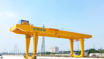
Overhead Launching Gantry
The main gantry structure sits above the bridge deck level — typically on temporary support legs that rest on the pier tops or on the completed deck.
Segments are lifted from below (from delivery vehicles on the completed deck, or from barges/ground transport at the pier locations) using lifting trolleys that travel along the overhead gantry structure. The trolleys position each segment at its final location in the span under construction.
Advantages: the gantry structure does not interfere with the space below the bridge — useful when the bridge crosses a live highway, railway, or waterway that must remain operational during construction.
Disadvantages: the overhead structure must clear any obstructions above the bridge deck level — overhead power lines, for example — which can constrain the gantry’s height and route.
Underslung Launching Gantry
The main gantry structure runs below the bridge deck level — typically suspended from or supported by the pier heads, with the structure extending below the eventual deck soffit elevation.
Segments are lifted from below and the gantry’s lifting equipment positions them from underneath — raising segments up into position against the underside of the deck structure being completed.
Advantages: lower overall height profile — useful where overhead clearance constraints exist.
Disadvantages: the underslung structure occupies the space below the bridge during construction — problematic if that space must remain clear for traffic, navigation, or other uses during the construction period.
Part 3: The Launching Sequence
Step 1: Span Erection
With the gantry positioned spanning the current set of piers (typically the gantry’s front support rests on the pier ahead of the span under construction, and the rear support rests on the pier behind — or on the previously completed span):
For precast segmental construction: segments are delivered to the gantry (via the completed deck behind, or lifted from ground/water transport below) and placed sequentially along the span, typically working from each pier toward mid-span, with epoxy joints between segments and post-tensioning tendons stressed once all segments for the span are in place and the epoxy has cured.
For cast-in-place construction using a launching gantry-supported form traveler: the gantry supports formwork for the full span. Concrete is poured, cured, and post-tensioned before the form traveler releases and the gantry launches forward.
Step 2: Stressing and Span Completion
Once all segments (or the cast-in-place section) for the current span are placed and the joints/concrete have achieved adequate strength, post-tensioning tendons running through the segments (or through ducts in the cast-in-place section) are stressed. This stressing operation locks the segments together structurally and transfers the span’s self-weight load path from the temporary gantry support to the permanent pier bearings.
Only after stressing is complete and verified can the gantry release its support on the completed span and begin the launch to the next position.
Step 3: The Launch
The gantry’s rear support — currently on the pier behind the just-completed span (or on an earlier completed span) — releases and the gantry begins moving forward.
The launching mechanism typically uses: hydraulic strand jacks or hydraulic cylinders with stepping mechanisms that “walk” the gantry forward in increments, low-friction sliding surfaces (PTFE-faced bearings) at the support points to reduce the force required to slide the massive gantry structure, and a guidance system to maintain the gantry’s alignment with the bridge centerline during the launch.
The launch distance equals one span length — moving the gantry from its current position to span the next set of piers ahead.
Step 4: Repositioning and Repeat
Once the gantry has launched forward by one span length, its front support lands on the new forward pier and its rear support is now positioned on what was previously the front pier (now supporting the rear of the gantry over the just-completed span).
The gantry is now positioned to begin span erection for the next span. The sequence (Steps 1 through 4) repeats for every span in the bridge.
Part 4: Structural and Mechanical Components
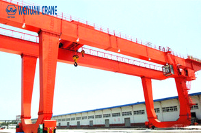
Main Girder or Truss
The primary structural element — a steel box girder or truss structure — must be designed for: the bending moments created by spanning across the piers with the segment-handling loads applied at various positions along its length, and the launching condition, where the support reactions move continuously as the gantry slides forward, creating a moving-load condition on the gantry’s own structure.
Lifting Trolleys (Overhead Type)
For overhead gantries: one or more lifting trolleys travel along the main girder, each capable of lifting a segment (40 to 200+ tonnes depending on the bridge design) and positioning it precisely at its final location — typically requiring multi-axis positioning (longitudinal, transverse, and vertical adjustment, plus rotation for skew alignment).
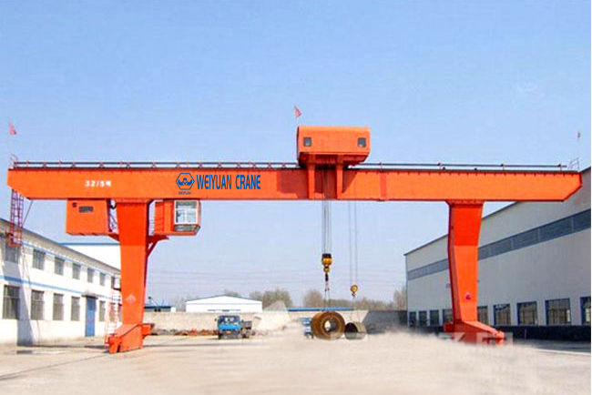
Support Legs and Launching Saddles
The gantry’s support points — front, rear, and sometimes intermediate auxiliary supports — rest on the pier tops or on the deck via launching saddles: steel assemblies incorporating the sliding surfaces, jacking points (for adjusting the gantry’s elevation to match the deck profile), and the connection to the gantry’s main structure.
Launching Drive System
The mechanism that moves the gantry forward — typically hydraulic strand jacks (which grip a steel strand anchored ahead of the gantry and pull the gantry forward incrementally) or hydraulic cylinder-and-clamp systems that achieve the same incremental “walking” motion.
Part 5: Span Length and Capacity Range
Typical Span Lengths
Launching gantries are designed for the specific span length of the bridge project — there is no “standard” launching gantry in the way there might be a standard workshop gantry crane. Typical highway and rail viaduct spans served by launching gantries: 30 to 60 metres per span, with the gantry length typically 1.5 to 2.2 times the span length to maintain stable support during the launch transition.
Segment Weight Capacity
Precast segment weights for typical highway viaducts: 40 to 100 tonnes per segment for standard two-lane highway sections. For wider sections (multi-lane highways, high-speed rail) or longer spans: 100 to 250 tonnes per segment.
The launching gantry’s lifting capacity must cover the heaviest segment in the project, plus the lifting frame/spreader beam weight, plus appropriate dynamic and handling margins.
Frequently Asked Questions
Q: Who typically owns a launching gantry — the bridge contractor or a specialized equipment supplier?
A: Both models exist. Large infrastructure contractors with ongoing viaduct construction programs often own their launching gantries as capital equipment, redeploying them across multiple projects. For single-project or shorter-duration work, specialized launching gantry suppliers design, fabricate, and lease the equipment to the contractor for the project duration, often including engineering support for the launching sequence design and operator training. Given the highly project-specific nature of launching gantry design (span length, segment weight, and site conditions all drive the specific design), close collaboration between the contractor and the gantry supplier or designer is essential from early in the project planning phase.
Q: How long does it take to launch a gantry from one span to the next?
A: The launch operation itself — the incremental sliding movement across one span length — typically takes 1 to 3 days depending on the gantry size, span length, and launching system capacity. However, the complete cycle for one span — including segment erection, joint curing, post-tensioning, and the launch itself — typically takes 1 to 2 weeks for standard highway viaduct spans. This cycle time is the key production metric for viaduct construction planning: a project with 100 spans at a 10-day cycle time requires approximately 1,000 working days (continuous single-gantry operation) — driving decisions about whether multiple gantries should be deployed simultaneously on long projects.
Q: Can a launching gantry navigate curves and varying span lengths?
A: Yes, within design limits established for the specific gantry. Horizontal curves are accommodated through the gantry’s guidance system, which steers the support points along the curved alignment during launching. Varying span lengths (common on real viaducts, where pier spacing is not perfectly uniform) are accommodated within a design range — typically the gantry can handle spans within approximately ±20% of its nominal design span length without major reconfiguration. Spans significantly outside this range may require gantry modifications (extending or shortening the main structure) between use on different portions of the project.