


Articulating Jib Crane Guide: Dual-Arm Reach Geometry, Dead Zone Elimination & CMAA Duty Classification
Introduction
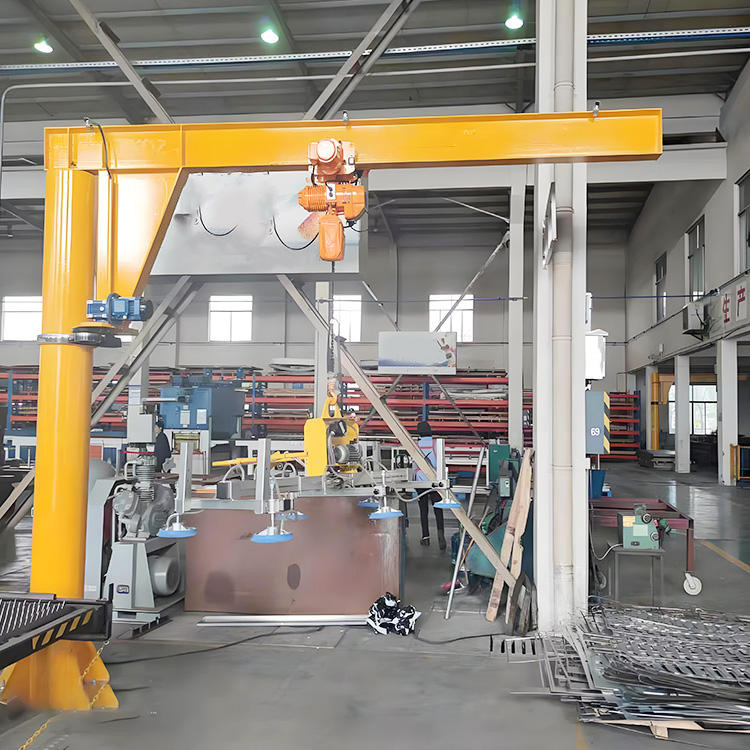
An articulating jib crane looks like someone took a normal jib crane and added an elbow. A primary arm reaches out from a mast or wall, and a second arm hinges off the end of the first, free to swing on its own pivot. The operator can fold the load in close, reach it around a machine, or tuck it behind an obstruction. To most people, that second joint just looks like extra reach. That is exactly the misunderstanding that leads buyers to specify the wrong crane and then wonder why it behaves nothing like the rigid jib they expected.
A rigid jib crane swings a load through a clean arc at a fixed radius. An articulating jib does something fundamentally different: it follows the load. The second arm lets the hook travel in almost any path the operator chooses — straight lines, tight curves, around corners — because the two arms work together like a human shoulder and elbow. That freedom is the whole point of the design. It is what lets an articulating jib reach into a deep machine, place a part precisely on a fixture, and then fold back out of the way. But that same freedom changes the structural problem completely. The load no longer applies a predictable moment at a fixed radius. It applies a moment that shifts as the two arms reposition, with the worst case occurring when both arms stretch out in line — a reach the operator can create by accident as easily as on purpose.
That is where standard rigid-jib thinking fails. A rigid jib is sized for one outreach. An articulating jib must be sized for its maximum combined reach, the fully extended position where the primary and secondary arms add together into the longest lever the crane can form. Specify it as though it were a rigid jib at its nominal radius, and the connection, the bearings, and the foundation are all undersized for the position the crane reaches dozens of times a day. Add the low pivot friction that makes articulating arms so easy to move — and so prone to drifting if not controlled — and you have a crane that feels effortless to the operator while quietly overloading the structure that holds it.
An articulating jib crane is a reach-geometry problem first and a lifting device second. It must be sized for the worst-case extended reach, not the nominal one. Its two pivot bearings must handle smooth, low-effort rotation without letting the load drift uncontrolled. Its dead zone — the area close to the mast that the folded arms cannot reach — must be understood and designed around. And every connection must be detailed for the high cycle counts these cranes rack up, because their ease of use means operators move them constantly.
This guide covers the complete framework for specifying an articulating jib crane: the application categories and where each fits, the corrosion and load specifications, the dual-arm reach geometry that governs the design, CMAA duty classification, the dead zone and pivot bearing considerations unique to articulating cranes, the common design errors that cause early failure, and a 2026 price reference. By the end you will understand why the second arm changes everything — and why the extended-reach position, not the nominal one, is the number that matters.
Part 1: Application Categories
The way an articulating jib crane is used sets its capacity, its reach geometry, and how its dual arms must be balanced. These cranes are chosen specifically where a rigid jib cannot follow the load, so the application almost always involves precise positioning, obstructed access, or both. Three categories cover most installations.
Category 1: Precision Assembly and Workstation Cells
The classic articulating jib serves an assembly cell where a part must be placed accurately onto a fixture, into a machine, or onto a moving line. The operator guides the load along a path the rigid jib’s fixed arc could never follow.
- Typical capacity: 80 kg to 500 kg.
- Typical reach: 2 to 4 m combined.
- Articulation: primary arm and secondary arm each rotating, often 200° primary and 360° secondary.
- Duty: heavy cycling, frequently CMAA Class D, because assembly lifts repeat constantly through a shift.
The defining feature is positioning freedom at high cycle count. The operator may move the load hundreds of times per shift, so the pivot bearings and connections see enormous cycle totals even at modest load.
Category 2: Machine-Tending and Obstructed-Access Lifting
An articulating jib tends a machine where the load must reach in past a guard, a fence, or part of the machine itself — a path no rigid arm can take. The second arm folds around the obstruction to reach the work point.
- Typical capacity: 150 kg to 1 tonne.
- Typical reach: 3 to 5 m combined.
- Articulation: primary arm reaching to the machine, secondary arm reaching in past the obstruction.
- Duty: moderate to heavy, CMAA Class C–D, matched to the machine’s production rate.
The defining challenge is reaching around something. The crane is chosen precisely because a straight arm cannot get to the load, which makes the secondary arm’s independent swing the whole reason for the purchase.
Category 3: Under-Bridge and Tight-Footprint Coverage
An articulating jib serves a work area beneath a bridge crane or in a confined bay where a rigid jib’s swept arc would collide with adjacent equipment. The folding arms let the crane cover an irregular work zone without sweeping a full circle into its neighbors.
- Typical capacity: 250 kg to 1 tonne.
- Typical reach: 3 to 5 m combined.
- Articulation: arms folded to keep the load within a defined irregular envelope.
- Duty: moderate, CMAA Class C, supporting a larger crane or fitting a packed floor.
The defining factor is the irregular work envelope. Because the two arms can fold, the crane covers an oddly shaped area that a rigid jib’s circle would either miss or overrun.
Bottom line: match the crane to its real need — precision cells cycle hard, machine-tending jibs reach around obstructions, and tight-footprint jibs cover irregular zones — and remember that all three buy the second arm for positioning freedom, which is exactly what drives the cycle count and the geometry.
Part 2: Corrosion Protection and Load Specifications
Two specifications frame every articulating jib before the structural design begins: how it resists its environment, and how its loads are defined. The load definition is more involved here than on a rigid jib, because the two arms create more than one critical position.
Defining the Load Inputs
The load that sizes an articulating jib is never just the rated load, and it is never just one position. The structural design uses a combined figure evaluated at the worst geometry:
- Rated load (SWL): the maximum working load on the hook.
- Hoist and trolley weight: dead weight at the end of the secondary arm, which adds to the moment at full extension.
- Primary arm self-weight: acting at its center of gravity.
- Secondary arm self-weight: acting at its own center of gravity, which moves as the arm rotates.
- Dynamic factor: an impact allowance per the duty class, amplifying the lifted load for the jerk of hoisting and the acceleration of swinging two arms.
The governing case is the fully extended position — primary and secondary arms in line, hoist at the far end, rated load on the hook, dynamic factor applied. This produces the longest lever and the maximum moment at the mast or wall connection. Sizing for the nominal folded reach instead is the single most common specification error on these cranes.
Indoor Coating Specification
Most articulating jibs work indoors in assembly and machine-tending cells, where the corrosion demand is modest — ISO 12944 category C2 to C3. A standard system suffices:
- Surface preparation to a clean, sound profile.
- Zinc-rich or epoxy primer.
- Polyurethane or alkyd topcoat.
- Total dry film thickness around 120–160 µm.
Outdoor and Aggressive Environments
Where an articulating jib serves a loading point, a washdown area, or an outdoor process bay, the environment climbs to ISO 12944 C4 to C5-M (marine), and the coating steps up:
- Surface preparation: Sa 2.5 near-white blast.
- Zinc-rich epoxy primer (~80 µm) for galvanic protection.
- Epoxy intermediate barrier coat (~100 µm).
- Polyurethane or polysiloxane topcoat (~80 µm).
- Total dry film thickness ~260 µm.
For severe marine or chemical service, hot-dip galvanizing the arms before painting adds decades of base protection.
Hardware, Pivots, and Fastener Specification
- Indoor: zinc-plated or galvanized fasteners are adequate.
- Outdoor C4–C5: hot-dip galvanized fittings, or type 316L stainless steel for the most exposed connections.
- Pivot bearings: the two articulation pivots are the heart of the crane and must be sealed against contamination and packed with grease matched to the environment. In washdown service, sealed bearings with marine-grade grease prevent water washing the lubricant out of the joints the operator relies on for smooth movement.
Bottom line: define the load at the fully extended worst-case geometry, not the folded nominal reach, then match the coating and hardware to the real environment — and protect the two pivot bearings carefully, because they carry both the load and the easy movement that defines the crane.
Part 3: Dual-Arm Reach Geometry and Load Transfer
This is the heart of articulating jib design and the part that separates it from every rigid jib. The crane has two arms on two pivots, and the way they combine sets both the reach the operator gains and the moment the structure must resist. Understanding this geometry is what stops a buyer from sizing the crane for the wrong position.
How the Two Arms Combine
An articulating jib has a primary arm pivoting at the mast or wall, and a secondary arm pivoting at the end of the primary arm. The hook hangs from the end of the secondary arm. The operator positions the load by rotating each arm independently, and the hook can travel almost any path within the combined reach.
The total reach changes with the angle between the two arms:
- Fully extended (arms in line): maximum reach, equal to the primary arm length plus the secondary arm length. This is the longest lever the crane can form — and the worst case for the structure.
- Folded (arms at an angle): shorter reach, with the load pulled in closer to the mast. The moment at the mast is lower here.
This variable reach is the crane’s great advantage and its central design trap. The operator gains a wide, flexible working envelope, but the structure must be sized for the one position where both arms line up.
The Governing Moment at the Mast
The moment at the mast or wall connection is the load times its horizontal distance from the mast centerline. At full extension that distance is the sum of both arm lengths:
Moment at mast = (Rated load + hoist weight) × (primary length + secondary length) × dynamic factor + arm self-weights × their respective distances
Because the extended reach is so much longer than the folded reach, the moment at full extension can be dramatically higher than at the nominal working position. A crane that feels lightly loaded when the operator works close in is, at full stretch, applying its design-governing moment.
Worked Example
Consider a 250 kg articulating jib with a 2.5 m primary arm and a 1.5 m secondary arm, hoist weight 60 kg, dynamic factor 1.2.
At full extension, the reach is 2.5 + 1.5 = 4.0 m:
- Load + hoist = 310 kg → 310 × 4.0 × 1.2 = 1,488 kg·m (arm self-weights ignored here for clarity).
At a folded position where the secondary arm doubles back so the hook sits only 2.0 m from the mast:
- 310 × 2.0 × 1.2 = 744 kg·m.
The fully extended position generates twice the moment of the folded one — for the identical load. A crane sized for the 744 kg·m folded case would be overloaded by 100% every time the operator stretches both arms out in line, a position reached routinely in normal use.
Why the Connection Must Be Sized for Full Extension
The lever arm is set by the operator, not the designer. Nothing physically stops the arms lining up, and operators will extend them to reach far points constantly. The mast connection, the pivot bearings, and the foundation or wall must therefore all be sized for the fully extended moment, with the dynamic factor applied. This is the defining rule of articulating jib design.
Balancing and Drift Control
The same low-friction pivots that make the arms easy to move also let the load drift if the arms are not balanced or restrained. Quality articulating jibs use:
- Balanced pivot resistance: enough bearing friction or a controlled detent to hold a position without the arms creeping under the load’s own pull.
- Optional position locks: mechanical detents at the pivots for tasks needing a held position.
Without this, the operator fights the load’s tendency to swing toward the lowest point, which defeats the precision the crane was bought for.
Deflection Control Across Two Arms
Deflection adds up across both arms. Each arm bends under load, and the secondary arm’s deflection compounds the primary arm’s, so the hook drops more at full extension than either arm alone would suggest. Articulating jibs are held to a combined tip-deflection limit so the load does not sag noticeably at full reach, which usually requires stiffer arm sections than a single-arm strength check would demand.
Bottom line: the two arms combine to a maximum reach when in line, that extended position creates the governing moment, the connection and bearings must be sized for it rather than the folded reach, and the low-friction pivots must be balanced so the load does not drift.
Part 4: CMAA Compliance and Duty Classification
An articulating jib is not exempt from the duty classification that governs every crane — and because these cranes are so easy to move, their cycle counts are often higher than any other jib type. The class you assign sets the dynamic factor, the fatigue detailing of the two pivots, and the service life.
Why Duty Class Matters More Here
The whole appeal of an articulating jib is effortless positioning, and that ease drives constant use. An assembly-cell jib whose arms swing with a light push will be moved far more often than a stiff rigid jib doing the same work. The cycle count — not the load size — drives the fatigue demand on the two pivot bearings and their connections, and the duty class is how that demand is captured. Treating an articulating jib as casual equipment outside classification is a reliable way to crack a pivot weld within a year or two.
CMAA Service Classes Applied to Articulating Jibs
CMAA service classifications run from Class A (infrequent, light) through Class F (severe, continuous), based on load magnitude and the number of load cycles over the crane’s design life:
- Class A–B: infrequent or light-duty lifting — occasional service jibs.
- Class C: moderate, regular use — light assembly and tight-footprint jibs.
- Class D: heavy production use — busy assembly and machine-tending jibs cycling constantly.
- Class E–F: severe, continuous duty — possible on high-throughput automated cells.
Most articulating workstation jibs land in Class C to D, and the busiest precision cells reach the upper end because of their relentless cycle count.
The Dynamic Impact Factor
CMAA practice amplifies the lifted load with an impact factor for the dynamic effects of hoisting and the acceleration of two swinging arms. Typical values rise with duty class:
- Class A–B: around 1.10
- Class C–D: 1.15 to 1.20
- Class E–F: 1.20 to 1.25
This factor feeds directly into the extended-reach moment in Part 3 — a higher duty class produces a higher moment for the same load, raising the demand on both pivots and the foundation.
Fatigue Detailing of the Two Pivots
The duty class sets the fatigue category of the critical details, and an articulating jib has two pivot connections instead of one: the primary pivot at the mast, and the secondary pivot at the joint between the arms. Both rotate constantly and carry load through every cycle. The secondary pivot is especially demanding, because it carries the full hook load through a small, hard-working joint that moves on nearly every operator action. Both pivot welds and bearing seats must be checked against the allowable stress range for the expected cycles, following AISC or equivalent fatigue provisions. A pivot adequate for a single static lift can still crack under millions of reversals if the fatigue category is wrong for the duty.
Bottom line: classify an articulating jib honestly by its high real cycle count — most fall in Class C–D — and use that class to set the dynamic factor and to detail both pivot connections, especially the hard-working secondary joint, as fatigue-loaded.
Part 5: Dead Zone and Pivot Bearing Considerations
Two features unique to articulating jibs shape how they are specified and used: the dead zone the folded arms cannot reach, and the pivot bearings that make the whole crane work. Neither exists on a rigid jib, and ignoring either undermines the crane.
What the Dead Zone Is
An articulating jib cannot place the hook everywhere within its outer reach. Close to the mast, the two arms cannot fold tightly enough to bring the load right up to the column — there is a dead zone, a circular area around the mast that the hook simply cannot enter. The folded arms collide with each other or with the mast before the hook reaches that close.
The dead zone radius depends on the arm lengths and the maximum fold angle of the secondary arm. A crane with a long secondary arm can fold the load in tighter, shrinking the dead zone; a crane with a short secondary arm leaves a larger unreachable circle near the mast.
Designing Around the Dead Zone
The dead zone is not a defect — it is an inherent feature of the geometry — but it must be planned for:
- Position the mast so the work points all fall outside the dead zone. Mounting the crane too close to the work can leave the nearest work point inside the unreachable circle.
- Choose arm lengths so the combination of reach and fold suits the actual work envelope, not just the maximum reach.
- Confirm the full working envelope — both the outer reach and the inner dead zone — against the real layout before installation, because a crane that reaches far enough but cannot get close enough is just as useless as one that cannot reach.
This inner-reach limit is the mirror image of the rigid jib’s simple outer arc, and overlooking it is a common planning mistake.
The Pivot Bearings Are the Crane
On a rigid jib, one slewing bearing carries the load and provides rotation. An articulating jib has two pivots, and they define both how the crane feels and how long it lasts:
- Primary pivot: at the mast or wall, carrying the full load moment and providing the primary arm’s swing.
- Secondary pivot: at the joint between the arms, carrying the hook load and providing the secondary arm’s swing.
Both must rotate smoothly under load with low effort — that low effort is the whole point of the crane — while still carrying their share of the load without play.
Why the Bearings Must Be Both Smooth and Tight
There is a tension at the core of pivot design. The bearings must turn easily so the operator can position the load with a light hand, but they must have no slack, or the load drifts and positioning accuracy is lost. Quality articulating jibs resolve this with precision sealed bearings that combine low rotational friction with zero radial play, and with balanced resistance that holds a position without the operator fighting drift. Cheap bearings that are either too stiff (defeating the ease the crane was bought for) or too loose (letting the load wander) are the most common reason an articulating jib disappoints in service.
Maintaining the Pivots
Because both pivots work constantly, they need a maintenance routine a rigid jib does not:
- Lubrication on a schedule, with grease matched to the environment, to keep the bearings smooth and free of play.
- Sealing kept intact so contamination and washdown water cannot reach the bearing surfaces.
- Play checks to catch developing slack before it grows into positioning error or accelerated wear.
Bottom line: the dead zone near the mast must be planned around by positioning and arm-length choice, and the two pivot bearings — which must be smooth, tight, sealed, and maintained — are the components that make the crane both work and last.
Part 6: Common Design Errors
Most articulating-jib failures and disappointments trace back to a handful of repeatable mistakes, and nearly all of them come from treating the crane like a rigid jib. Each is avoidable with the right check before the crane goes up.
Error 1: Sizing for Nominal Reach Instead of Full Extension
The most common and most damaging error sizes the crane for its folded working reach, ignoring that the operator can extend both arms in line. The connection, pivots, and foundation are then overloaded every time the arms line up — a routine position, not a rare one.
Avoid it: size the whole load path for the fully extended moment with the dynamic factor applied, as shown in Part 3.
Error 2: Ignoring the Dead Zone in Layout
The crane is positioned without checking the inner dead zone, and the nearest work point turns out to fall inside the unreachable circle around the mast. The crane reaches far points fine but cannot get close to the very spot it was installed for.
Avoid it: map both the outer reach and the inner dead zone against the real work layout before fixing the mast position.
Error 3: Specifying Cheap Pivot Bearings
Low-cost bearings are fitted to save money. Too stiff, they defeat the easy positioning that justified the crane; too loose, they let the load drift and ruin accuracy. Either way the crane disappoints the operators it was bought for.
Avoid it: specify precision sealed pivot bearings with low friction and zero play, and treat them as the crane’s most important components.
Error 4: Treating the Load as a Single Static Position
The structure is checked at one position only, missing that the moment changes as the arms move and peaks at full extension. A check at the folded position passes while the extended position is overloaded.
Avoid it: evaluate the moment across the full range of arm positions and design for the worst case.
Error 5: Skipping Duty Classification on an Easy-to-Move Crane
Because the arms swing so easily, the crane is assumed to be lightly worked and is never classified. In reality the ease of movement drives a very high cycle count, and the secondary pivot cracks from fatigue.
Avoid it: classify honestly by real cycle count — usually Class C–D — and detail both pivots as fatigue-loaded joints.
Error 6: Neglecting Pivot Maintenance
The two pivots are installed and forgotten. Over time the bearings dry out, develop play, and the smooth positioning degrades into a stiff or sloppy joint that wears fast.
Avoid it: put both pivots on a lubrication, sealing, and play-check schedule from day one.
Bottom line: most articulating-jib problems come from sizing for the wrong reach, ignoring the dead zone, skimping on bearings, checking only one position, skipping classification, or neglecting pivot maintenance — each cheap to fix in design and expensive to fix after the crane underperforms or cracks.
Part 7: 2026 Price Reference
These ranges frame budgeting only. Final pricing depends on capacity, arm lengths, mounting type, duty class, environment, and bearing quality. Contact WEIYUAN for a quote matched to your installation.
| Articulating jib configuration | Indicative capacity & reach | 2026 price range (USD) |
|---|---|---|
| Light wall-mounted articulating jib, indoor | 80–150 kg, 2–3 m | $1,800 – $4,500 |
| Standard wall-mounted articulating jib, indoor | 250 kg, 3–4 m | $4,000 – $8,500 |
| Mast-mounted (freestanding) articulating jib, indoor | 250–500 kg, 3–4 m | $6,500 – $14,000 |
| Medium-duty articulating jib, indoor | 1 t, 4–5 m | $12,000 – $26,000 |
| Ceiling-mounted articulating jib, indoor | 250–500 kg, 3–4 m | $9,000 – $20,000 |
| Outdoor / washdown articulating jib (C4–C5 coating, sealed bearings) | 250 kg–1 t, 3–4 m | $14,000 – $32,000 |
Cost comparison takeaways:
- An articulating jib costs more than a rigid jib of the same capacity and outer reach, because the second arm adds a pivot, a bearing, and a more complex structure — but it buys positioning freedom no rigid jib can match.
- The pivot bearings are where the money matters most. The price gap between a crane that positions smoothly for a decade and one that drifts or stiffens within a year is largely the quality of the two bearings — under-spend here and the whole investment disappoints.
- An outdoor marine-grade coating with sealed bearings adds roughly 40 to 60% over a standard indoor finish, but against years of corrosion and contaminated pivots on an exposed crane, it is among the cheapest insurance in the specification.
Frequently Asked Questions
Q: When should I choose an articulating jib over a standard rigid jib crane?
A: Choose an articulating jib when you need to follow a path or reach around something a straight arm cannot. A rigid jib swings the load through a fixed arc at a set radius, which is perfect for simple in-and-out lifts. An articulating jib’s second arm lets the hook travel almost any path — straight lines, tight curves, around a machine guard, or into a deep fixture — and fold the load in close when needed. If your work involves precise placement onto fixtures, tending a machine past an obstruction, or covering an irregular area that a full circle would overrun, the articulating jib earns its higher cost. If your lifts are simple arcs at a fixed radius, a rigid jib is cheaper and entirely adequate.
Q: Why must an articulating jib be sized for its fully extended reach?
A: Because the operator, not the designer, sets the lever arm. The two arms can line up into the crane’s maximum reach, and that fully extended position creates the largest moment at the mast — often double the moment of a folded working position for the same load. Nothing physically stops the arms extending, and operators reach far points constantly, so the fully extended position is routine, not rare. If the crane is sized for its nominal folded reach instead, the connection, pivot bearings, and foundation are overloaded every time the arms stretch out in line. Sizing the entire load path for the fully extended moment with the dynamic factor applied is the defining rule of articulating jib design.
Q: What is the dead zone and why does it matter?
A: The dead zone is the circular area around the mast that the hook cannot reach, because the two arms cannot fold tightly enough to bring the load right up to the column. Every articulating jib has one — it is an inherent feature of the folding geometry, not a defect. It matters because a crane can have plenty of outer reach yet still be unable to get close to the work if the work point falls inside that inner circle. Before fixing the mast position, map both the outer reach and the inner dead zone against your real layout, and choose arm lengths so every work point falls in the reachable band between them. Overlooking the dead zone is a common planning mistake that leaves a crane unable to serve the very spot it was installed for.
Q: Why does the load drift or feel hard to position on my articulating jib?
A: Both problems point to the pivot bearings. If the load drifts on its own, the bearings are too loose or the pivot resistance is not balanced, so the load swings toward the lowest point and the operator fights it. If positioning feels stiff and heavy, the bearings are too tight or have dried out, defeating the easy movement the crane was bought for. Quality articulating jibs use precision sealed bearings that combine low friction with zero play, plus balanced resistance that holds a position without creeping. The fix is to check the bearing condition and lubrication, confirm there is no developing play, and — if cheap bearings were fitted originally — replace them with precision sealed units. The two pivots are the components that make or break how the crane feels.
Q: How much maintenance does an articulating jib need compared to a rigid jib?
A: More, because it has two working pivots instead of one slewing bearing, and both move on nearly every operator action. Put both pivots on a regular lubrication schedule with grease matched to the environment, keep their seals intact so contamination and washdown water cannot reach the bearing surfaces, and check periodically for developing play before it grows into positioning error or accelerated wear. The secondary pivot at the joint between the arms works hardest and deserves the closest attention. None of this is onerous — it is a few minutes on a schedule — but skipping it lets the smooth, precise movement that justified the crane degrade into a stiff or sloppy joint that wears fast.