
Overhead Crane for Nuclear Power & Heavy Process Industry
Introduction
The overhead crane in a nuclear power plant is not simply a material handling tool that happens to be installed in a regulated facility. It is a safety-critical system whose failure during a design basis event — an earthquake, a beyond-design-basis accident, or a fuel handling operation — could directly contribute to radiological consequences that no other safety system can fully mitigate. This distinction between safety-critical and production-critical lifting equipment drives a set of design, qualification, procurement, and maintenance requirements that are more demanding than any other crane specification discipline in industrial practice.
A nuclear-grade polar crane in the reactor containment building of a pressurized water reactor may spend 90% of its operating life stationary — it is needed only for refueling operations every 18 to 24 months and for major maintenance events. But when it is needed, it must perform with absolute reliability under conditions — seismic loading, high radiation fields, extended post-accident environments — that have no counterpart in any commercial industrial crane application. The engineering investment required to deliver this reliability under these conditions is what separates nuclear overhead cranes from all other lifting equipment categories.
This guide provides the complete technical reference for overhead cranes in nuclear power and heavy process industry applications: the safety classification framework that governs nuclear crane design, the seismic and radiation qualification requirements, the single failure proof design philosophy that is unique to nuclear lifting applications, the specific crane types serving different nuclear facility functions, the analogous requirements in other heavy process industries, and the procurement and qualification process that delivers documented assurance of crane performance.
Part 1: Nuclear Crane Safety Classification — The Governing Framework
Nuclear Safety Class vs Non-Safety Class
The first and most consequential classification decision for any crane in a nuclear facility is whether the crane is required to perform a safety function — a function whose failure could prevent safe shutdown, maintain core cooling, or contain radioactive material during or after a design basis event.
Cranes that perform safety functions are classified as nuclear safety related (NS-related or Q-class) and are subject to the full quality assurance requirements of 10 CFR 50 Appendix B (in the U.S.) and equivalent regulatory frameworks internationally. Cranes that do not perform safety functions — general maintenance cranes in auxiliary buildings away from the safety envelope — are classified as non-safety related (non-Q) and may be designed and procured to standard industrial specifications, though they are still subject to nuclear facility administrative controls.
In practice, the cranes most commonly classified as nuclear safety related include: the reactor building polar crane (used for reactor pressure vessel head lift during refueling), fuel handling building bridge cranes (used for new and spent fuel assembly movement), safety injection pump room maintenance cranes in some plant configurations, and spent fuel pool cranes.
NRC 10 CFR 50 Appendix B Quality Assurance Requirements
U.S. nuclear power plant equipment classified as safety related must be designed, procured, fabricated, installed, and tested under a quality assurance program meeting the 18 criteria of 10 CFR 50 Appendix B. For overhead cranes, this means:
Design control: The crane’s design basis, including all loads (gravity, seismic, thermal, radiation), must be documented, reviewed, and approved by qualified engineers. Design changes must follow the same controlled process.
Procurement document control: Every purchased component — from structural steel to hoist limit switches — must be procured against specifications that invoke the applicable quality requirements, and the supplier’s compliance must be verified.
Material traceability: All structural steel, welds, and safety-related components must be traceable from the material certification through fabrication to installation. The traceability chain must be documented and retrievable for the plant’s operating license life.
Testing and inspection: Each crane must pass a documented inspection and load test program before initial operation, with all test results recorded and retained permanently.
NUREG-0554: The Single Failure Proof Standard
NUREG-0554 (Single-Failure-Proof Cranes for Nuclear Power Plants), published by the U.S. Nuclear Regulatory Commission, defines the design philosophy that is unique to nuclear lifting applications and distinguishes nuclear cranes from all other industrial lifting equipment.
The single failure proof criterion states that the crane lifting system must be designed such that no single credible failure of any component can cause a load drop. This is accomplished through redundancy in every element of the load path — not simply as a backup, but as a fully independent parallel load path that carries the full load if the primary path fails.
A single failure proof hoist design implementing NUREG-0554 typically includes:
Dual independent hoist mechanisms: Two complete, independent hoist units mounted on the same crane bridge, each capable of supporting the full rated load independently. Any single mechanical failure — rope break, drum shaft failure, gearbox failure — in one hoist is contained by the other.
Four-part rope reeving minimum: Each hoist uses multiple-part reeving so that the failure of any single rope part does not cause a load drop. The remaining rope parts carry the full load while the crane is safely lowered to a rest position.
Redundant brakes: Each hoist has two independently actuated brakes, either of which alone can hold 125% of rated load. No single brake component failure causes uncontrolled load descent.
Load path structural redundancy: All primary structural members in the load path are designed with sufficient redundancy that the failure of any single member does not cause collapse of the load-carrying structure.
IAEA Safety Standards SSG-8
The International Atomic Energy Agency’s Safety Guide SSG-8 (Design of Overhead Lifting Equipment for Nuclear Facilities) provides the international standard for nuclear crane design that is referenced by nuclear regulatory authorities in countries without their own national standard. SSG-8 aligns with NUREG-0554 in the single failure proof philosophy but extends the guidance to cover the complete lifecycle — design, procurement, operation, periodic testing, and aging management — of nuclear lifting equipment.
Part 2: Seismic Design Requirements
Nuclear Facility Seismic Classification
Nuclear power plant structures, systems, and components are classified into seismic categories based on their safety function and the consequences of their failure during a seismic event. Safety-related overhead cranes are typically assigned to Seismic Category I — the most demanding classification — requiring that they remain functional (or in a controlled state) following a Safe Shutdown Earthquake (SSE), the most severe earthquake the facility is designed to withstand.
The SSE is defined as the maximum earthquake that is reasonably expected to occur at the site during the plant’s operating life, based on a probabilistic seismic hazard analysis. Peak ground accelerations for SSE events at nuclear plant sites in the United States typically range from 0.1 g to 0.5 g, with some sites in high-seismicity regions designed for 0.6 g or higher.
ASCE 7 and IEEE 344 Seismic Qualification
Seismic qualification of nuclear overhead cranes is accomplished through one of three methods specified in IEEE 344 (Recommended Practice for Seismic Qualification of Class 1E Equipment for Nuclear Power Generating Stations):
Analysis: Finite element analysis or equivalent dynamic analysis of the crane structure and components under the applicable seismic input motions. The analysis must demonstrate that all structural members remain within allowable stress limits and that no component exceeds its deformation limit under the combined normal operating plus SSE loading combination.
Testing: Physical seismic simulation testing of the crane or its components on a shake table, demonstrating functionality before, during, and after the simulated seismic event.
Experience data: Demonstrating through documented historical performance data that the crane’s design and components have been shown to function correctly following seismic events of comparable intensity. This method is applicable for equipment that has been previously installed in seismically active sites and has a documented performance history.
Seismic Restraint Provisions
Overhead cranes in nuclear facilities require seismic restraint systems that prevent the crane from traveling off its runway during a seismic event and that limit the dynamic loads imposed on the crane structure during seismic excitation. Seismic restraints include:
Positive rail retainment: End truck wheel flanges and rail head geometry are specifically designed to prevent wheel lifting from the rail under vertical seismic uplift forces — a failure mode that standard industrial crane end trucks are not designed to resist.
Parking locks: Mechanical locking devices that secure the crane bridge to the runway rails and the trolley to the bridge rails when the crane is in its normal parked position, preventing displacement during seismic motion.
Lateral seismic stops: Positive-stop devices at the ends and sides of the crane travel paths that prevent the crane from impacting building structure with damaging force during seismic motion.
Part 3: Radiation Environment Adaptation
How Radiation Degrades Standard Equipment
Nuclear facilities expose lifting equipment in reactor and fuel handling areas to elevated levels of ionizing radiation — gamma radiation and neutron flux — that progressively degrade materials and components not selected for radiation resistance.
Electrical insulation: Standard PVC and rubber cable insulation undergoes radiolysis — chain scission in the polymer matrix — causing brittleness, cracking, and loss of insulating properties at accumulated doses above approximately 10^4 to 10^5 Gray depending on the insulation material. Cable replacement programs must be scheduled based on the cumulative dose at the cable location.
Lubricants: Mineral and synthetic hydrocarbon lubricants degrade under radiation through oxidation and viscosity change. At high cumulative doses, lubricants can thicken to the point of interfering with gear and bearing operation. Greases and oils for nuclear crane applications must be selected from qualified radiation-resistant formulations — PFPE synthetic lubricants provide superior radiation resistance for the highest-dose applications.
Seals and gaskets: Elastomeric seals (O-rings, shaft seals) undergo radiation-induced hardening that causes loss of sealing function. For cranes in high-dose areas, stainless steel labyrinth seals or other non-elastomeric sealing designs replace conventional elastomeric seals.
Radiation-Resistant Component Specification
Nuclear overhead cranes in radiation zones use specifically qualified components:
Motors: Cast iron or stainless steel frame motors with radiation-resistant winding insulation (Class H with specialized radiation-resistant varnish systems rated for cumulative doses exceeding 10^6 Gray). Air-cooled rather than liquid-cooled to avoid radioactive coolant contamination risk.
Sensors and instrumentation: Position sensors, load cells, and limit switches qualified for operation in elevated radiation fields — typically Class 1E qualified for nuclear safety-related applications.
Control cables and wiring: Cross-linked polyethylene (XLPE) or ethylene-propylene rubber (EPR) insulated cables with radiation-qualified jackets, specified to the applicable IEEE 323 (Qualifying Class 1E Equipment for Nuclear Power Generating Stations) requirements.
Part 4: Nuclear Power Plant Crane Applications
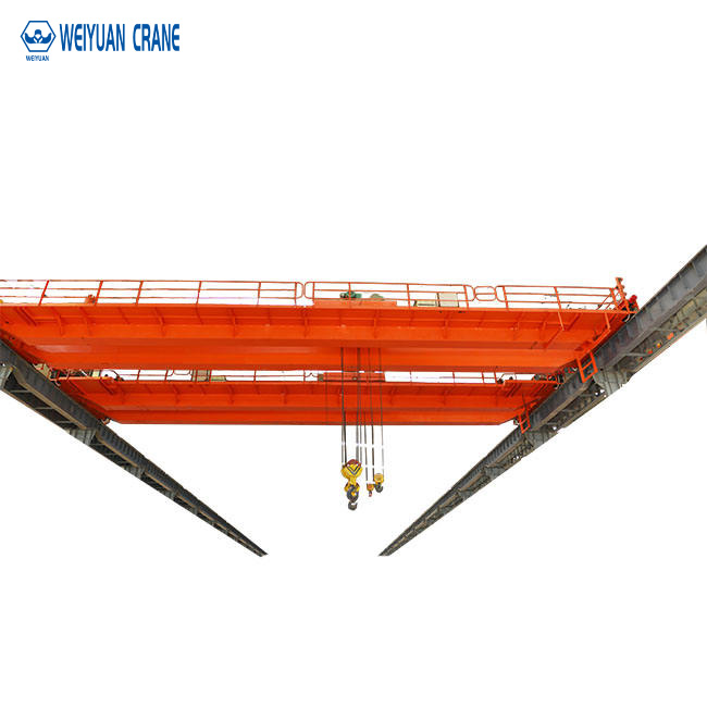
Reactor Building Polar Crane
The polar crane — named for its circular runway in the cylindrical reactor containment building — is the nuclear plant’s most safety-critical overhead crane. It serves the reactor pressure vessel head lift during each refueling outage and must be capable of this critical lift with absolute reliability.
Key specifications of a typical polar crane:
- Capacity: 50 to 200 tons depending on reactor vessel head weight (PWR heads typically 90 to 180 tons; BWR reactor heads typically 50 to 120 tons)
- Runway: Circular, typically 30 to 60 meters diameter, mounted on a reinforced concrete ledge on the containment wall
- Design standard: NUREG-0554 single failure proof; 10 CFR 50 Appendix B quality assurance
- Seismic qualification: IEEE 344 analysis or testing for the plant’s SSE level
- Lift speed: Very slow (0.1 to 0.5 m/min) for the reactor head lift — precision positioning in a confined space with radiation monitoring equipment in close proximity
Fuel Handling Building Bridge Cranes
Bridge cranes in the fuel handling building (new fuel storage, spent fuel pool, and fuel transfer areas) handle fuel assemblies containing highly radioactive spent nuclear fuel. These cranes must provide the precise, shock-free handling that prevents damage to spent fuel assemblies — which could release radioactive material — while operating above the spent fuel pool in an elevated radiation and humidity environment.
Key specifications:
- Capacity: 5 to 20 tons (fuel assembly plus below-hook tooling)
- NUREG-0554 compliance: Required for cranes lifting spent fuel above the spent fuel pool
- Underwater visibility provisions: Camera systems and lighting for fuel assembly operations conducted with the assembly submerged in the spent fuel pool
- Corrosion resistance: Stainless steel construction or equivalent corrosion protection for components in the high-humidity, boric acid environment of the spent fuel pool area
Steam Generator Replacement Cranes
Steam generator replacement — a major nuclear plant life extension operation involving the removal and replacement of the primary heat exchangers — requires specialized heavy-lift overhead crane systems that are installed temporarily in the steam generator compartment and the reactor building.
These replacement cranes are among the heaviest overhead crane lifts in the nuclear industry: steam generators for large PWRs weigh 250 to 500 tons, and the lift path requires navigating through precise openings in containment walls with clearances measured in centimeters. Custom-engineered lifting systems with computer-controlled multi-point lifts are standard for these operations.
Part 5: Heavy Process Industry Analogous Requirements
Petroleum Refining and LNG Facilities (Hazardous Area)
Petroleum refining and LNG processing facilities contain classified hazardous areas where flammable gas atmospheres may be present. Overhead cranes operating in ATEX Zone 1 or NEC Class I Division 1 areas require full explosion-proof certification for all electrical components — equivalent to the ATEX Group II Ex d or Ex e certification described in the explosion-proof guide.
In addition to explosion protection, cranes in chemical processing environments require enhanced corrosion protection for exposure to hydrogen sulfide, hydrocarbon vapors, and acidic process condensates. ISO 12944 C5-I (industrial) or C5-M (marine/offshore) corrosion protection categories are the minimum appropriate specification for cranes in active process areas.
Steel and Aluminum Smelting (High Temperature)
Electric arc furnace (EAF) steel mills and aluminum smelters operate overhead cranes in ambient temperatures of 40°C to 80°C or higher near the furnace taphole area. At these temperatures, standard motor insulation approaches its rated temperature limit before adding any motor heating from operation, requiring motors rated for elevated ambient temperature — typically Class H insulation with IP55 or better enclosure protection against metallic fume and steam.
Molten metal splash protection is a unique requirement in these applications: crane structural components, electrical enclosures, and hoist wire rope must be protected against the radiant heat and direct splash of molten steel or aluminum. Stainless steel heat shields, refractory-coated structural sections, and wire rope specifically rated for high radiant heat environments are all standard provisions for furnace-area overhead cranes.
Aluminum Smelting: Electromagnetic Field Effects
Aluminum smelters use very high direct currents (100,000 to 500,000 amperes per reduction cell) that create powerful magnetic fields throughout the potroom. Standard induction motors and electronic control systems are adversely affected by these fields — induced voltages in motor windings create parasitic currents that heat the windings, and magnetic saturation in motor cores reduces efficiency and torque.
Overhead cranes operating in aluminum potrooms require specially designed motors with increased magnetic core area and winding configurations that resist magnetic saturation, and control systems with adequate electromagnetic shielding. The crane structure itself must be verified not to create magnetic flux disruptions that would affect the electrochemical reduction process in nearby cells.
Part 6: Procurement and Qualification Process
Third-Party Inspection and Surveillance
Nuclear-grade overhead crane procurement requires independent third-party inspection (TPI) at the crane manufacturer’s facility, verifying that the manufacturing process complies with the procurement specification and the quality assurance program. The TPI scope typically includes: material certification review and traceability verification, weld inspection (visual, dimensional, and non-destructive testing), dimensional inspection of critical interfaces, witness of factory acceptance testing, and review of quality records.
Factory Acceptance Testing (FAT) — Nuclear Grade
The factory acceptance test for a nuclear-grade overhead crane is substantially more comprehensive than the standard industrial crane FAT:
Load test: Proof load test at 125% of rated capacity (or as specified for single failure proof cranes — sometimes 110% with the redundant hoist carrying the balance) with complete documentation of test loads, dates, and inspector signatures.
Seismic restraint verification: Functional testing of all seismic parking locks, lateral stops, and wheel retainment provisions.
Single failure proof demonstration: Sequential disabling of each single failure proof redundant element (one brake, one hoist, one rope part) while demonstrating that the remaining elements hold the rated load without exceeding allowable deformation.
Radiation environment simulation: For cranes in high-radiation zones, extended operation at elevated temperature (simulating worst-case ambient conditions) may be required to demonstrate component performance under realistic operating conditions.
Qualification Documentation Package
The documentation package that must accompany a nuclear-grade overhead crane from factory acceptance through installation, startup, and the plant’s operating life is substantially more extensive than standard industrial documentation:
Design basis document: The complete design basis including all loads, load combinations, applicable codes and standards, and the design analysis demonstrating structural and functional adequacy.
Material certifications: Certified mill test reports (CMTRs) for all structural steel and pressure boundary materials, traceable to each crane component.
Weld records: Complete weld traveler documentation for all structural welds, including welder qualification, procedure qualification, inspection records, and non-destructive testing results.
Test records: Factory acceptance test data, seismic qualification test reports or analysis reports, and all calibration records for test instrumentation.
ASME NQA-1 compliance package: Documentation demonstrating that the entire procurement, fabrication, testing, and installation process was conducted under a quality assurance program meeting ASME NQA-1 (Quality Assurance Requirements for Nuclear Facility Applications).
Frequently Asked Questions
Q: What is the single failure proof criterion and how does it differ from standard industrial safety factors?
A: Standard industrial overhead cranes are designed with safety factors — the structural members and components are sized to carry several times the rated load before failure. This provides resistance to overloading but does not prevent a load drop if a critical component (such as the wire rope or the hoist gearbox) fails at rated load. The single failure proof criterion requires that no single credible failure of any component can cause a load drop — through redundancy in every element of the load path, not through increased safety factors in individual components. It is a fundamentally different design philosophy, not simply a higher version of the standard approach.
Q: Can a standard industrial overhead crane be upgraded to meet nuclear safety requirements?
A: Generally no. Nuclear safety related cranes must be designed and fabricated to nuclear quality assurance requirements from the beginning — the material traceability, design documentation, and fabrication quality records that nuclear certification requires cannot be retroactively generated for a crane that was designed and built to standard industrial specifications. Specific components (hoists, controls, limit switches) can be replaced with nuclear-qualified units as part of a documented modification program, but the entire crane cannot be retroactively qualified to nuclear safety class.
Q: How frequently must nuclear overhead cranes be load tested?
A: NUREG-0612 (Control of Heavy Loads at Nuclear Power Plants) requires that nuclear safety related cranes be load tested before each use for heavy loads (loads that could damage safety-related equipment if dropped) if the crane has not been used within the preceding 12-month period. Annual load testing is therefore the standard practice for most nuclear safety related cranes. In addition, full proof load testing at 125% rated capacity is required after any significant repair or modification.