



Cranes
Jib Crane Foundation Design: Column Base Plate, Anchor Bolt, and Concrete Block Specifications
Introduction
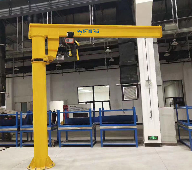
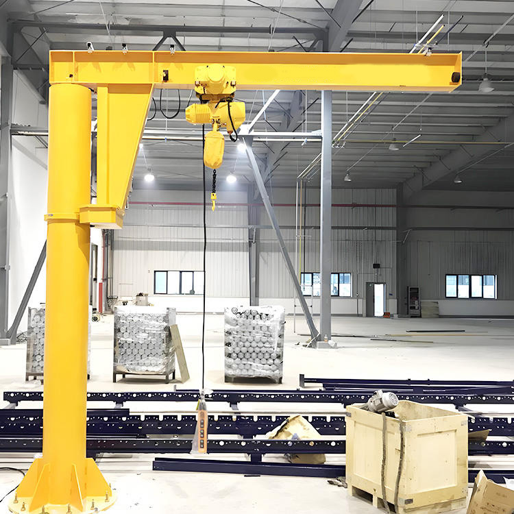
A metal fabrication shop I reviewed had specified a good jib crane — a 3-tonne pillar-mounted unit with a 5-metre boom, correctly duty-rated for the busy workstation it served. The crane arrived on time, the pillar was plumb at installation, and it lifted its first loads exactly as promised. The trouble showed up in the foundation nobody had engineered.
The installer had poured a concrete block that looked substantial — about a metre square and a metre deep — sized by eye against “what a 3-tonne crane should need.” What nobody had run was the overturning moment. A 3-tonne load at 5 metres of reach applies a 15-tonne-metre moment to that foundation, and the block was less than half the size that moment demanded. Within a year the block had begun to rock under load, tilting a few millimetres each time the crane swung a heavy lift out to the tip. The pillar leaned with it. Loads started drifting off their marks when the crane rotated, the anchor bolts worked loose in their oversized holes, and the grout under the base plate crumbled to powder. By month eighteen the shop was breaking out the whole foundation and pouring a properly engineered block — at three times the cost of doing it right the first time.
Nobody had been reckless. The crane was right. The base plate was standard. But the foundation strings together the base plate, the anchor bolts, the grout, and the concrete block, and the overturning moment finds the weakest of them. On a jib crane, that moment is the whole story — a jib converts every lift into load times reach, and that moment lands squarely on a foundation most buyers treat as an afterthought.
This is Part 2 of our three-part jib crane series, following Part 1 on jib crane types and selection. Here we cover the foundation itself — the load calculations that size everything, the base plate and anchor bolt design, the concrete block, the geotechnical bearing beneath it, the grouting and leveling, and the inspection tolerances that confirm the whole thing was built right. Part 3 will close the series on jib crane installation, operation, and maintenance.
What you’ll take away:
- How to calculate the overturning moment, anchor bolt tension, and base plate loads a jib applies
- How to size the concrete block against overturning, sliding, and bearing
- What geotechnical bearing capacity your foundation actually needs
- How to specify anchor bolt embedment depth and grade (ASTM F1554)
- How grouting and leveling decide whether the base plate carries load evenly
- The inspection and acceptance tolerances that confirm a sound foundation
- 2026 pricing so the civil scope doesn’t ambush your budget
Part 1: Foundation Load Calculations — The Overturning Moment Governs Everything
Before you size a single component, you calculate the forces the jib applies to the foundation. On a jib crane, one force dominates all the others: the overturning moment. Get this number right and the base plate, bolts, and block all follow from it. Get it wrong — or skip it, as the fabrication shop’s installer did — and every component downstream is under-built.
Step 1: The Overturning Moment
A jib lifts a load at a horizontal distance from the pillar’s centerline, and that force acting at a distance creates a moment that tries to tip the whole crane over. The moment is the load multiplied by its reach, plus the boom’s own dead weight acting at its center of gravity.
   OVERTURNING MOMENT ON A PILLAR JIB

        [load W]────────[boom]────┐
          │                       │
          │◄──── reach R ────────►│
                             ┌────┴────┐
                             │ PILLAR  │  ← moment M = W × R
                             │         │     (+ boom self-weight)
                           ══╧═════════╧══
                           FOUNDATION resists M
Take the fabrication shop’s crane as the worked example:
- Rated load W = 3,000 kg (29.4 kN)
- Boom reach R = 5 m
- Load moment = 29.4 kN × 5 m = 147 kN·m
- Boom self-weight, say 400 kg at a 2.5 m center = 3.92 kN × 2.5 m ≈ 9.8 kN·m
- Total service overturning moment ≈ 157 kN·m (about 16 tonne-metres)
Now apply the dynamic impact factor — a jib in service snatches loads, so codes add an allowance (commonly 1.15 to 1.25 for electric hoists per CMAA). At a 1.25 factor, the design moment climbs to roughly 196 kN·m. That amplified moment is what the foundation must resist, not the tidy static number.
Step 2: The Vertical Load
The vertical load down the pillar is simpler: the load, plus the boom and hoist dead weight, plus impact.
- Load + impact: 29.4 kN × 1.25 = 36.75 kN
- Boom, hoist, pillar dead weight: say 12 kN
- Total vertical design load ≈ 49 kN
Step 3: Anchor Bolt Tension From the Moment
Here’s where the moment turns into a force that pulls the foundation apart. The overturning moment tries to lift one side of the base plate — and the anchor bolts on that side resist it in tension, while the concrete on the opposite side takes compression. The bolt group acts as a couple resisting the moment.
   MOMENT → BOLT TENSION COUPLE

     M ↻
   ┌──────────────────┐
   T ↑                ↓ C     T = tension (uplift side)
   ●                  ▓       C = compression (bearing side)
   │◄──── bolt lever arm d ──►│
        BASE PLATE
The tension in the uplift-side bolts is approximately the moment divided by the lever arm between the bolt group and the compression zone. For a base plate with bolts spaced so the effective lever arm d ≈ 0.5 m:
- Uplift force T ≈ M ÷ d = 196 kN·m ÷ 0.5 m = 392 kN total on the tension side
- Split across, say, 4 tension-side bolts ≈ 98 kN per bolt
That per-bolt tension is what sizes the bolt diameter and — critically — its embedment depth (Part 4). The vertical load offsets a small part of the uplift, but on a jib the moment overwhelms it, so the bolts see net tension on every heavy lift.
Mini-takeaway: the overturning moment (load × reach, plus boom weight, times impact) is the number that drives the entire foundation. It sets the anchor bolt tension, the base plate size, and the concrete block dimensions. Calculate it first — everything else is derived from it.
Part 2: Base Plate Design
The base plate is the interface between the steel pillar and the concrete block. Its job is to spread the pillar’s concentrated vertical load and moment across enough concrete area that the bearing stress stays within the concrete’s capacity, and to anchor the tension bolts that resist uplift. Undersize it and the concrete crushes under the compression edge; misdetail the bolt holes and the moment tears the plate.
Sizing the Plate for Bearing
Under the overturning moment, the base plate doesn’t bear evenly — it bears hardest along the compression edge, exactly opposite the tension bolts. The peak bearing stress there must stay within the allowable concrete bearing strength, which ACI 318 relates to the concrete’s compressive strength f’c:
- Allowable bearing ≈ 0.65 × φ × f’c (with the confinement bonus where the plate is smaller than the block)
- For f’c = 25 MPa concrete, allowable bearing lands in the range of ~11 to 15 MPa depending on confinement
The plate plan dimensions are sized so the peak edge-bearing stress from the combined vertical load and moment stays under that limit. A jib base plate is therefore often larger than intuition suggests — the moment concentrates the load onto one edge, so you need generous area to keep that edge stress in check.
Plate Thickness
The plate must also be thick enough not to bend under the bearing pressure and the bolt tension. Two checks govern:
- Bending under compression bearing — the plate cantilevers beyond the pillar footprint, and the bearing pressure tries to curl it up.
- Bending under bolt tension — the tension bolts pull the plate up against the pillar’s welded connection.
   BASE PLATE UNDER MOMENT

    tension bolts        compression edge
        ●  ●                  ▓▓▓▓
   ═════╪══╪══════[PILLAR]══════════   ← base plate
        │  │                  ▲
     pull up              bearing pushes up
        → plate must be thick enough to not bend
A typical jib base plate runs 25 to 50 mm thick depending on capacity and reach. The engineer sizes it from the calculated bending — a plate too thin dishes under load and lets the pillar rock even on a sound block.
Bolt Hole Detailing
The bolt holes carry the tension into the plate, and their detailing matters more than buyers expect:
- Hole size — oversized holes (for erection tolerance) must be closed up with plate washers welded over them once aligned, or the bolts sit loose and the plate shifts under the cyclic moment. Loose bolts in oversized holes are exactly how the fabrication shop’s plate started to walk.
- Edge distance — bolts need adequate distance from the plate edge so the plate doesn’t tear out around them.
- Welded connection to the pillar — the pillar-to-plate weld carries the full moment and must be a full-penetration detail on a high-duty jib.
Mini-takeaway: size the base plate area against the concentrated edge-bearing the moment creates, thick enough to resist bending from both bearing and bolt tension, with bolt holes properly detailed and closed up. A generous, stiff plate spreads the moment; a thin, loosely detailed one lets the pillar rock.
Part 3: Concrete Block Sizing — Resisting Overturning, Sliding, and Bearing
The concrete block is what actually keeps the jib upright. Its size and weight resist the overturning moment, its base area spreads the load into the soil, and its mass resists sliding. This is the component the fabrication shop guessed at — and the one where guessing costs the most.
The Three Checks Every Block Must Pass
A jib foundation block must satisfy three independent stability checks against the design overturning moment:
1. Overturning stability. The block’s own weight, acting at its center, creates a stabilizing (righting) moment that must exceed the crane’s overturning moment by a safety factor — commonly 1.5 or greater.
   OVERTURNING vs RIGHTING MOMENT

           overturning M ↻
        ┌──────────────────┐
        │                  │
        │   CONCRETE BLOCK │  weight Wb acts at center
        │        ●         │  righting moment = Wb × (B/2)
        │                  │
        └────────┬─────────┘
          tipping edge  │◄─ B/2 ─►│
   Require: Wb × (B/2) ≥ 1.5 × M
For the worked example (design moment ~196 kN·m), and taking a righting arm of half the block width:
- Required righting moment = 1.5 × 196 = 294 kN·m
- With a 2.0 m wide block, righting arm = 1.0 m, so required block weight = 294 kN
- Concrete at 24 kN/m³ → required volume ≈ 12.25 m³
- A block roughly 2.0 m × 2.0 m × 1.5 m deep ≈ 6 m³ falls short — you need closer to 2.2 m × 2.2 m × 1.6 m plus the soil-bearing check below
That’s already far larger than the ~1 m³ the installer poured, which is precisely why it rocked.
2. Soil bearing. The block plus crane loads press into the soil, and the peak bearing pressure (highest under the compression edge, because of the moment) must stay within the soil’s allowable bearing capacity — covered in Part 5.
3. Sliding. The horizontal thrust (from load swing, wind on an outdoor jib) tries to slide the block; the friction under the base and any passive soil resistance must exceed it by a safety factor around 1.5.
Reinforcement
The block isn’t plain concrete. It needs reinforcement to carry the tension the moment and the anchor bolt pull-out generate within it:
- A reinforcing cage tying the anchor bolts into the body of the block, so bolt uplift engages the block’s mass rather than pulling out a shallow cone of concrete
- Top and bottom mats sized to ACI 318 for the bending the eccentric load induces
- Adequate cover for the environment (more for outdoor or marine exposure)
Mini-takeaway: the block passes three checks — overturning (righting moment ≥ 1.5 × design moment), soil bearing, and sliding — and it’s reinforced to tie the bolts into its mass. Size it by calculation against the moment, never by eye. A block that looks big enough usually isn’t, because the moment is larger than intuition suggests.
Part 4: Anchor Bolt Embedment Depth and Grade
The anchor bolts carry the tension from the overturning moment out of the base plate and deep into the concrete block. Two things decide whether they hold: the grade (the steel’s strength) and the embedment depth (how far into the concrete they reach). Get either wrong and the bolts either snap or pull a cone of concrete out of the block.
Bolt Grade — Specify to ASTM F1554
Anchor bolts are specified under ASTM F1554, which defines three grades by yield strength:
| Grade | Yield strength | Typical use |
|---|---|---|
| Grade 36 | 36 ksi (250 MPa) | Light-duty jibs, low tension |
| Grade 55 | 55 ksi (380 MPa) | Moderate-duty, the common jib choice |
| Grade 105 | 105 ksi (725 MPa) | Heavy-duty, high-tension freestanding jibs |
The grade is chosen so the bolt’s tensile capacity comfortably exceeds the calculated per-bolt tension (98 kN in our worked example) with the code safety factor applied. Don’t substitute an unmarked bolt of unknown grade to save money — the whole moment resistance runs through these bolts.
Embedment Depth — Governed by Concrete Breakout
Here’s the failure mode that surprises people: a bolt of adequate steel strength can still fail by pulling a cone of concrete out of the block if it isn’t embedded deep enough. ACI 318, Appendix D (Chapter 17 in current editions) governs this concrete breakout check.
   CONCRETE BREAKOUT CONE

        bolt tension T ↑
              │
        ══════╪══════  ← base plate
        ╲     │     ╱
         ╲    │    ╱   ← breakout cone (~35° from bolt axis)
          ╲   │   ╱
           ╲  │  ╱     Embed depth hef must be deep
            ╲ │ ╱       enough that cone capacity > T
             ╲│╱
   ───────────●───────── anchor at depth hef
The breakout capacity grows with embedment depth: the deeper the bolt, the larger the concrete cone it would have to pull out, and the more force that takes. For jib cranes, embedment depths commonly run 12 to 20 bolt diameters, and often 300 to 600 mm or more on heavier units. The engineer calculates the required hef from the per-bolt tension, and the block depth (Part 3) must accommodate it with cover to spare.
Two details that make or break the anchorage:
- Anchor type — cast-in-place anchors (headed bolts or hooked bolts set before the pour) develop far more reliable tension capacity than post-installed expansion anchors, and are strongly preferred for the sustained, cyclic tension a jib applies.
- Tie into the reinforcement — anchoring the bolts into the reinforcing cage (Part 3) engages the block’s mass and prevents the shallow breakout cone, dramatically increasing capacity over a bolt floating in plain concrete.
Mini-takeaway: specify bolt grade to ASTM F1554 so the steel carries the tension, and embedment depth to ACI 318 so the concrete doesn’t break out — commonly 12 to 20 diameters, cast-in-place, tied into the reinforcing cage. The bolt and the concrete around it are one system; size them together.
Part 5: Geotechnical Bearing Requirements
Everything above assumes the soil beneath the block can carry the load without settling. That assumption is the one the fabrication shop never checked — and settlement is what let the block rock in the first place. The block spreads the crane loads into the ground, and the ground has to be strong enough and stable enough to hold it level.
The Peak Bearing Pressure Isn’t Uniform
Because the overturning moment shifts the load toward one edge, the bearing pressure under a jib foundation is not uniform — it peaks under the compression edge and drops toward the uplift edge.
   BEARING PRESSURE UNDER MOMENT

        M ↻
   ┌──────────────────────┐
   │    CONCRETE BLOCK     │
   └──────────────────────┘
   ░░▒▒▓▓████████            ← pressure peaks at compression edge
   low                high
   Peak pressure must stay < allowable soil bearing
The peak edge pressure — not the average — must stay within the soil’s allowable bearing capacity. In a worse case, if the moment is large enough relative to the vertical load, part of the base can try to lift off entirely, concentrating all the load on a smaller area and spiking the peak pressure. The block must be sized so the whole base stays in contact and the peak stays under the limit.
Typical Allowable Bearing Values
Allowable bearing capacity depends entirely on the soil, and it must come from a geotechnical assessment, not a table. As rough orientation only:
| Soil type | Indicative allowable bearing |
|---|---|
| Soft clay / fill | 50 – 100 kPa (often inadequate — needs improvement) |
| Firm clay | 100 – 200 kPa |
| Dense sand / gravel | 200 – 400 kPa |
| Rock | 1,000+ kPa |
The fabrication shop’s block sat partly on compacted fill — the worst case — which settled unevenly and tilted the whole foundation. A soil investigation would have flagged it before the pour.
Settlement, Not Just Strength
Bearing capacity prevents outright failure, but differential settlement is the subtler killer. If one edge of the block settles more than the other — because the soil varies, or because the moment loads one edge harder — the block tilts, the pillar leans, and loads drift when the crane rotates. A jib is unforgiving of tilt because the boom amplifies a tiny base rotation into a large hook displacement at full reach.
For outdoor jibs, add the usual site factors: found the block below the frost line in cold climates, and provide drainage so water doesn’t soften the supporting soil.
Mini-takeaway: get a geotechnical assessment before you size the block, design the base so the peak edge pressure stays within the soil’s allowable bearing, and guard against differential settlement — because a jib turns a small base tilt into a large hook drift. Never assume the soil; verify it.
Part 6: Grouting and Leveling
With the block poured and cured and the pillar set on its anchor bolts, one step remains that decides whether the base plate actually carries load evenly: the grout beneath it. This is the detail that looks trivial and quietly wrecks foundations when it’s skimped — the fabrication shop’s grout crumbled because it was the wrong material, poorly placed.
Why the Grout Matters
The base plate is set slightly above the concrete on leveling shims or nuts, leaving a gap of 25 to 50 mm. That gap is filled with non-shrink grout, which does two jobs:
- Transfers the compression load from the base plate into the concrete block across the full plate area, not just where the plate happens to touch high spots. Without full-contact grout, the compression edge (which carries the heaviest bearing under the moment) bears on point contacts and crushes.
- Locks the plate level so the pillar stays plumb and the boom stays horizontal.
Specify Non-Shrink Grout
Ordinary sand-cement mortar shrinks as it cures, leaving voids under the plate — exactly the crumbled, load-bearing-nothing condition the shop ended up with. Specify a non-shrink cementitious grout (or an epoxy grout for high-duty or vibration-prone installations), with a compressive strength at least equal to the block concrete, commonly 40 to 60 MPa. It must flow fully under the plate with no trapped voids.
   GROUT UNDER BASE PLATE

        [PILLAR]
   ══════════════════   ← base plate
   ▓▓▓▓▓▓▓▓▓▓▓▓▓▓▓▓▓▓   ← non-shrink grout (25–50 mm, full contact)
   ████████████████████ ← concrete block
        anchor bolts through both
Leveling the Plate
Before grouting, the plate is leveled precisely using the leveling nuts on the anchor bolts or steel shims:
- The plate must be level within a tight tolerance (Part 7), because any tilt here is amplified along the boom into hook drift.
- Once level and verified, the grout is placed to fill the gap completely, and only after it cures are the anchor nuts torqued to their final specification.
Mini-takeaway: the grout carries the compression load and locks the plate level — specify non-shrink (or epoxy) grout, place it with full contact and no voids, level the plate precisely before grouting, and torque the bolts only after the grout cures. Skimp the grout and the compression edge crushes, exactly where the moment loads it hardest.
Part 7: Inspection and Acceptance Tolerances
A foundation that looks finished isn’t accepted until it’s verified. These are the checks and tolerances you build into the purchase order and tie final payment to — the documented proof that the base plate, bolts, block, and grout were built as designed. Skipping this acceptance step is how the fabrication shop’s guessed-at foundation passed into service unchallenged.
What to Verify, and to What Tolerance
| Check | What it confirms | Typical tolerance |
|---|---|---|
| Pillar plumb | Pillar is vertical | ≤ 1/500 of height (≈ 2 mm per metre) |
| Base plate level | Plate is flat and level | ≤ 1.5 mm across the plate |
| Anchor bolt position | Bolts match the plate template | ±3 mm from plan location |
| Anchor bolt projection | Enough thread for nut + washer | Per drawing, no shortfall |
| Bolt torque | Bolts tensioned to spec | Per manufacturer torque value |
| Grout contact | No voids under plate | 100% contact, hammer-sound test |
| Concrete strength | Block reached design f’c | Cylinder/cube test ≥ f’c at 28 days |
| Block dimensions | Block built to size | Per drawing, no undersize |
The Sequence That Matters
The order of operations is part of the acceptance:
- Verify concrete strength from test cylinders before loading the foundation — never load a block that hasn’t reached design strength.
- Confirm bolt position and projection against the base plate before setting the pillar.
- Level the plate and verify before grouting.
- Place and cure the grout, then hammer-test for voids.
- Torque the anchor bolts to spec only after grout cure.
- Load-test the crane at 125% of rated capacity, with the foundation observed for any movement, cracking, or bolt slip.
Tie the Load Test to the Foundation
The proof load test isn’t only a crane check — it’s the foundation’s final exam. With 125% of rated load out at full reach (the worst-case moment), watch for any tilt of the pillar, any crack propagating in the block, any grout distress, or any bolt movement. A foundation that shows any of these under proof load is rejected until corrected. Require the whole acceptance documented, with cylinder results, alignment survey, torque records, and the load test certificate.
Mini-takeaway: make a documented acceptance — concrete strength, plumb, level, bolt position, torque, grout contact, and a 125% proof load test — a condition of the purchase order with payment tied to it. It’s the cheapest insurance against the fabrication shop’s outcome, where nobody checked and the foundation failed in service.
Part 8: 2026 Cost Reference for Jib Crane Foundations
Use these as planning figures to build a realistic budget for the foundation scope — the part of a jib crane project most often under-quoted or excluded from the crane price. Actual costs vary with capacity, reach, soil conditions, site access, and region. Always get a site-specific quote, but budget against these ranges so the civil work doesn’t ambush your project.
| Foundation element | Scope | 2026 planning range (USD) |
|---|---|---|
| Geotechnical assessment | Soil investigation + bearing report | $2,500 – $10,000 |
| Concrete block (light jib, ≤ 1 t) | Excavation, rebar, concrete, per block | $2,000 – $6,000 |
| Concrete block (moderate, 2–5 t) | Excavation, rebar, concrete, per block | $5,000 – $15,000 |
| Concrete block (heavy freestanding, 5–20 t) | Large engineered block, per block | $12,000 – $45,000+ |
| Base plate (supply, fabricated) | Sized plate with bolt holes + welds | $600 – $4,000 |
| Anchor bolts, cast-in (ASTM F1554) | Bolt set, per foundation | $400 – $3,500 |
| Non-shrink / epoxy grout | Material + placement | $300 – $1,500 |
| Foundation engineering design | Load calc, block + bolt design, drawings | $2,000 – $8,000 |
| Alignment + acceptance survey | Plumb, level, position verification | $800 – $3,000 |
| 125% proof load test | Test weights, rigging, certification | $1,000 – $5,000 |
Two budget realities worth flagging:
- The foundation can rival a light jib’s price. On a heavy freestanding unit, the engineered block, bolts, and geotechnical work are a genuine civil cost that can approach the crane itself. A crane quote that excludes the foundation isn’t cheaper — it’s incomplete.
- Engineering and geotechnical work are cheap insurance. A foundation design and a soil report together cost a fraction of the fabrication shop’s break-out-and-repour bill — which ran three times the original foundation cost, plus the workstation downtime. Design once, pour once.
Procurement tip: when you compare quotes, confirm the foundation scope line by line — geotechnical assessment, engineered design, block, bolts, grout, and the acceptance survey with a proof load test. A cheap headline number often excludes the soil report, the engineered block, or the load test, and those exclusions land back on your budget later. Normalize every quote to the same civil scope, and require the acceptance documentation as a condition of payment.
Frequently Asked Questions
Q: How big does a jib crane concrete foundation need to be?
A: It’s sized by calculation against the overturning moment, not by rule of thumb — which is exactly where most undersized foundations go wrong. Start with the moment (rated load × boom reach, plus the boom’s own weight, times the dynamic impact factor). The block must then pass three checks: overturning stability (its righting moment, from its own weight acting at half its width, must exceed the crane’s moment by a factor of about 1.5), soil bearing (the peak edge pressure must stay within the soil’s allowable capacity), and sliding resistance. For a 3-tonne crane at 5-metre reach, that typically means a reinforced block on the order of 2.2 m square by 1.6 m deep — far larger than the roughly 1 cubic metre intuition suggests. Have it engineered against your actual load, reach, and soil.
Q: What grade and embedment depth do jib crane anchor bolts need?
A: Specify the bolts to ASTM F1554 — Grade 55 is the common choice for moderate-duty jibs, Grade 105 for heavy freestanding units, and Grade 36 only for the lightest cranes. The grade is chosen so the bolt’s tensile capacity exceeds the per-bolt tension the overturning moment generates, with the code safety factor. Embedment depth is governed by the ACI 318 concrete breakout check — the bolt must reach deep enough that it can’t pull a cone of concrete out of the block — which commonly works out to 12 to 20 bolt diameters, often