
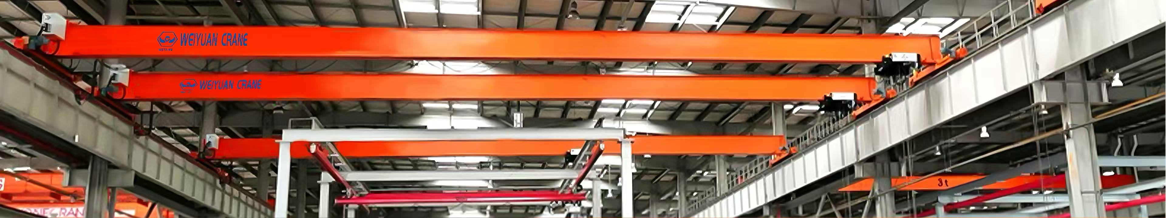
Cranes
Overhead Crane Anti-Sway Technology: How Active Control Cuts Positioning Time by 60%
Introduction
Every time an overhead crane stops, the load keeps moving. The hook decelerates. The load swings forward. The pendulum begins.
A 500 kg automotive component on a 4-metre rope swings ±180mm after a standard contactor-controlled stop. The crane operator waits for the swing to damp below ±30mm before attempting precision placement. That wait takes 15 to 25 seconds.
At 30 cycles per shift: 30 × 20 seconds = 600 seconds of non-productive waiting per shift. Per year at two shifts, 250 working days: 83 hours of crane time spent waiting for loads to stop swinging. In a facility where the crane is the production bottleneck, those 83 hours are 83 hours of lost output.
Active anti-sway technology eliminates this wait. The load arrives at the target position with ±20mm of residual swing — small enough for immediate precision placement without waiting. The 60% reduction in positioning time cited in this guide’s title is conservative for high-frequency production applications.
This guide explains exactly how anti-sway works, what hardware it requires, how to calculate its ROI, and when the investment is justified.
Part 1: The Physics of Load Swing
Why Loads Swing
A suspended load behaves as a pendulum. The rope is the pendulum arm. The hook and load are the pendulum bob. When the crane accelerates or decelerates, the inertia of the load causes the rope angle to change. The load swings.
The key equation: pendulum period T = 2π × √(L/g)
Where L is the rope length in metres and g is gravitational acceleration (9.81 m/s²).
Rope length 2 metres: T = 2π × √(2/9.81) = 2.84 seconds
Rope length 4 metres: T = 2π × √(4/9.81) = 4.02 seconds
Rope length 6 metres: T = 2π × √(6/9.81) = 4.92 seconds
Rope length 10 metres: T = 2π × √(10/9.81) = 6.35 seconds
The pendulum period defines the oscillation cycle. After a standard crane stop, the load completes one full swing cycle in T seconds and then continues oscillating with gradually reducing amplitude due to air resistance damping.
Air resistance damping in crane applications is very slow. A load on a 4-metre rope (T = 4 seconds) requires approximately 15 to 30 seconds to damp from ±200mm to ±30mm — depending on the load’s aerodynamic profile.
Why Operators Cannot Eliminate Swing Manually
An experienced crane operator uses anticipatory deceleration — they begin slowing the crane before reaching the target position, timing the deceleration so that the load swings forward and then reaches its rest position approximately at the target. This technique — sometimes called “hunting” — works reasonably well at low speeds and requires significant skill and practice.
It does not work reliably at high travel speeds. At 40 m/min travel speed, the crane covers 667mm per second. Timing a manual deceleration to produce the exact pendulum phase cancellation requires sub-second precision — beyond human reaction time.
It also fails when conditions change. A different hook height (different pendulum period), a different load weight, or a different travel distance — all change the timing calculation. A technique calibrated for one set of conditions fails when conditions change.
Part 2: Passive Reduction Methods
Two-Stage Braking (Operator Technique)
The operator reduces speed to approximately 5 to 10% of maximum (micro-speed) approximately one pendulum half-period before reaching the target, then stops from micro-speed when the hook is directly above the target.
Effect: reduces final swing amplitude by 60 to 80% compared to a single-stage stop from full speed. Does not eliminate swing.
Limitation: requires consistent application of the technique. Effectiveness varies with operator skill and fatigue. Does not scale to fully automated crane operation.
Speed Reduction
Reducing the crane’s maximum travel speed reduces the energy transferred to the pendulum during deceleration. At half the travel speed, the swing amplitude is approximately halved.
Limitation: directly reduces productivity. Halving the travel speed doubles the travel time component of each crane cycle.
Part 3: Active Anti-Sway — How It Works
Method 1: Input Shaping
Input shaping is the most widely implemented active anti-sway method in industrial overhead cranes.
The principle: instead of a single velocity command ramp, the control system generates a sequence of impulses specifically timed to cancel each other’s pendulum effects.
The simplest implementation — the Zero Vibration (ZV) input shaper — splits the original velocity command into two impulses. The first impulse creates a pendulum oscillation. The second impulse is timed to arrive exactly one half-period (T/2) later, with appropriate amplitude. The second impulse creates a pendulum oscillation of equal magnitude but opposite phase to the first. The two oscillations cancel, and the load arrives at rest with near-zero swing.
The timing depends on the pendulum period T, which depends on the rope length L. The control system continuously measures the rope length (from the hoist encoder) and recalculates T in real time. As the hook height changes during a lift, the input shaper updates automatically.
Performance: residual swing amplitude below ±20mm for standard production crane speeds. Some implementations achieve below ±10mm.
Robustness: input shaping is sensitive to errors in the estimated pendulum period. A 10% error in rope length measurement produces measurable residual swing. For applications requiring maximum robustness: use the Zero Vibration and Derivative (ZVD) shaper, which provides better tolerance to period uncertainty at the cost of slightly longer command duration.
Method 2: Feedback Control
Feedback anti-sway measures the actual swing angle in real time and applies corrective velocity commands to the crane drives.
Sensors used for swing angle measurement:
Rope angle sensor: a gyroscope or inclinometer mounted on the hook suspension detects the rope angle relative to vertical.
Vision system: a camera on the crane bridge tracks the hook block or load position and calculates swing angle from image processing.
Load cell array: multiple load cells in the hoist suspension detect the asymmetric loading that occurs when the rope swings — the angular component is extracted from the load asymmetry.
Control algorithm: a PID or model predictive controller uses the measured swing angle as feedback and adjusts the crane speed command to oppose the swing. When the load swings forward, the crane accelerates slightly in the same direction — reducing the rope angle. When the load swings back, the crane decelerates slightly.
Performance: comparable to input shaping for standard applications. Potentially superior for very long ropes or highly variable load masses where the input shaper’s period estimation has significant uncertainty.
Hardware requirement: the sensor adds cost and complexity compared to pure input shaping. Vision systems require cameras, lighting, and image processing hardware. Rope angle sensors require installation on the moving hook block — which must be wireless-connected to the control system.
Comparison: Input Shaping vs Feedback Control
Input shaping: lower hardware cost. Works from the hoist encoder alone — no additional sensors. Requires accurate rope length estimation. Standard for most production overhead crane applications.
Feedback control: higher hardware cost and complexity. Potentially more robust for variable conditions. Required for very high precision applications (±5mm or better). Standard for automated crane systems where human observation is not available to catch residual swing.
Most industrial anti-sway systems use input shaping as the primary method, with feedback augmentation for applications requiring the highest precision.
Part 4: Anti-Sway ROI Calculation
Baseline: Current Positioning Time per Cycle
A production overhead crane performs: travel to target position (variable time) + wait for swing to damp to acceptable level (15 to 25 seconds for standard contactor-controlled stop) + precision placement (5 to 10 seconds).
For a standard contactor-controlled crane at 30 production cycles per shift:
Total swing wait time per shift = 30 cycles × 20 seconds average = 600 seconds = 10 minutes.
With Active Anti-Sway
Residual swing after anti-sway stop: ±20mm. Acceptable for most production precision placement without additional waiting.
Swing wait time per shift = 30 cycles × 2 seconds residual settle = 60 seconds.
Annual Time Saving Calculation
Time saved per shift = 600 − 60 = 540 seconds = 9 minutes per shift.
At 2 shifts per day, 250 working days per year: 540 × 2 × 250 = 270,000 seconds = 75 hours per year.
This is 75 hours of crane capacity recovered per year. In a facility where the crane is the production bottleneck, these 75 hours generate additional production output. In a facility where the crane is not the bottleneck, these 75 hours reduce operator fatigue and allow the operator to perform other tasks during the travel phase.
Investment vs Return
Anti-sway system addition to a VFD-equipped overhead crane:
Software-only input shaping (upgrade to existing VFD): $3,000 to $8,000.
Full anti-sway system with new VFD: $15,000 to $35,000 for a standard production crane.
Production value of 75 recovered hours per year (at $500 to $3,000 per crane-hour depending on facility output):
At $1,000 per crane-hour: 75 × $1,000 = $75,000 per year.
Payback on $25,000 investment: 4 months.
At $200 per crane-hour (lower-value application):
Annual value = 75 × $200 = $15,000.
Payback on $25,000: 20 months.
The ROI analysis is application-specific. High-value production facilities — automotive, aerospace, precision manufacturing — justify anti-sway on almost any crane that performs more than 15 production cycles per shift.
Part 5: Hardware Requirements
VFD Is Mandatory
Input shaping requires variable speed control. The shaped velocity commands include intermediate speed levels — not just full speed and zero. A contactor-controlled (on/off) crane cannot implement input shaping.
A VFD is a prerequisite for any active anti-sway system. If the crane already has VFD control, the input shaping software can often be added as a parameter set or software module within the existing VFD — without new hardware.
Hoist Encoder for Rope Length Measurement
The input shaper’s timing depends on the current rope length. The rope length is calculated from the hoist encoder: encoder position at current hook height minus encoder position at maximum hook height, converted to rope length through the drum diameter and reeving factor.
Most modern electric hoists with VFD control already include an encoder on the hoist motor. This encoder provides the rope length data with no additional hardware.
Travel Encoder for Position Feedback
For anti-sway combined with positioning control (required for automated cranes): an absolute position encoder on the bridge travel drive and the trolley travel drive provides the position reference that the anti-sway system uses to time the shaped velocity commands.
Part 6: Applications and ROI by Industry
Automotive — Highest ROI
Press shop die changing: 25 to 40-tonne dies must be placed on press bolsters within ±5mm. Standard die changes require 4 to 8 minutes for swing damping and precision placement. Anti-sway reduces this to under 2 minutes.
Die change time saving per shift (10 die changes × 4 minutes saved): 40 minutes of press uptime recovered per shift.
Annual value at $5,000 per press-hour: 40 minutes × $83/minute × 2 shifts × 250 days = $1,660,000 annual value from one anti-sway crane.
This is the highest single-application ROI for anti-sway overhead crane technology.
Steel Service Center — High ROI
Coil handling cranes place steel coils on mandrels and transfer them between processing lines. The C-hook or magnetic lifter has significant mass. The combined load pendulum at 6 to 8-metre rope lengths has a 5 to 6-second period. Swing amplitude after a fast stop exceeds 400mm.
Anti-sway reduces coil placement time from 45 seconds to 15 seconds per cycle. At 40 coil transfers per shift: 800 seconds recovered. Annual value significant.
General Warehouse — Moderate ROI
Warehouse crane applications typically have lower cycle rates (10 to 20 per shift) and lower production value per crane-hour. Anti-sway ROI at $200 per crane-hour requires approximately 20 months payback — acceptable for a 15 to 20-year crane life but less compelling than automotive.
For warehouse applications: anti-sway is most justified when operator fatigue reduction and injury prevention are included in the value calculation alongside production throughput.
Frequently Asked Questions
Q: Does anti-sway work for all rope lengths?
A: Yes — within the practical range of overhead crane operation (typically 1 to 20 metres of rope). The input shaper recalculates its timing parameters as the rope length changes during each lift. At very short rope lengths (below 0.5 metres): the pendulum period is very short (below 1.4 seconds) and the window for effective input shaping narrows. At very long rope lengths (above 20 metres, in deep-shaft or high-bay applications): the pendulum period becomes long (above 9 seconds) and the input shaper requires longer shaped commands. Both extremes work — the performance may be slightly reduced compared to mid-range rope lengths.
Q: Can anti-sway be retrofitted to an existing crane that already has VFD?
A: Yes — in most cases. If the existing VFD is a current-generation model with accessible parameter programming, the input shaping algorithm can be added as a software feature. The VFD vendor or the crane controls specialist uploads the input shaping parameters and tunes the rope length measurement calibration. No mechanical modifications are required. Total retrofit cost for software-only input shaping: $3,000 to $8,000 including commissioning.
Q: Does anti-sway increase the crane’s structural loads?
A: Anti-sway input shaping slightly increases the peak crane velocity demand during the shaped command sequence (the two-impulse profile requires a brief speed increase above the nominal travel speed to achieve cancellation timing). This peak velocity increase is typically 5 to 15% above the nominal travel speed. Verify that the crane’s structural design can accommodate this velocity increase — particularly the dynamic wheel loads on the runway beam — before commissioning an anti-sway retrofit on an older crane.