
KBK Crane Installation Guide: Ceiling Suspension, Freestanding & Production Line Integration Step by Step
Introduction
One of the KBK crane system’s most compelling practical advantages is the simplicity of its installation. Where a conventional overhead crane installation involves structural engineering, field welding, heavy rigging, and multiple contractor trades working over several days, a KBK system installation is an assembly process — connecting standard components with standard tools in a logical sequence that a trained two-person maintenance crew can complete in one to two days for most workstation installations.
This simplicity is not accidental. The KBK system was specifically engineered for tool-based assembly without welding, cutting, or drilling into existing structure. All connections are bolted. All components arrive at the site with machined surfaces and pre-drilled holes that align to the system’s standard dimensions. The rail sections clip together with alignment sleeves that ensure joint smoothness. The suspension hardware adjusts to accommodate variations in ceiling height and beam position.
This guide provides the complete step-by-step installation reference for KBK crane systems: the pre-installation planning that ensures a successful installation, the two primary installation configurations (ceiling suspension and freestanding), the step-by-step assembly sequence for each, the electrical connection and commissioning procedure, integration with automated production lines, and the maintenance practices that keep the installed system performing reliably throughout its service life.
Part 1: Pre-Installation Planning
Step 1: Verify Building Structure Capacity
The most important pre-installation step — and the one most frequently skipped — is verifying that the building ceiling, roof beams, or other overhead structure can carry the KBK system suspension loads.
Calculate the suspension point load for each planned suspension point using the following formula:
Suspension point load = (Rail weight per meter × suspension spacing) + (Crane bridge weight ÷ number of runway suspension points) + (Rated crane capacity × dynamic factor ÷ number of runway suspension points)
The dynamic factor accounts for impact during acceleration and lifting. Use 1.15 for standard KBK systems operating at standard speeds.
Example: 1,000 kg KBK bridge crane, 10-meter runway with suspensions at 2-meter intervals (5 suspension points per side), 150 kg bridge weight, KBK-II rail at 8 kg/meter:
Suspension point load = (8 × 2) + (150 ÷ 5) + (1,000 × 1.15 ÷ 5) = 16 + 30 + 230 = 276 kg per suspension point.
Provide this load data to a licensed structural engineer for verification against the actual ceiling or beam structure at the installation site. Do not proceed with ceiling-suspended installation without this verification.
Step 2: Define the Rail Layout
Draw the rail layout on a floor plan showing:
- Runway rail centerlines and total length
- Bridge span (distance between runway rail centerlines)
- All suspension point locations
- Switch and curve locations (if applicable)
- Hoist position limits (marked on the rail to define the trolley travel range)
- All overhead obstructions that must be cleared (pipes, ducts, lighting, sprinklers)
Minimum clearances for the KBK system:
- Minimum clearance from rail to any fixed overhead obstruction: 50mm (rail top) and 100mm (end of rail sections)
- Minimum clearance from loaded hook travel path to any fixed obstruction: 200mm
- Minimum floor clearance: Load bottom must clear all floor-level equipment and personnel in the working area by at least 300mm when traveling at maximum speed
Step 3: Prepare the Component List
Using the rail layout drawing, generate the complete component list:
- Runway rail sections (specify quantity and length of each standard section)
- Rail joint alignment sleeves (one per joint)
- End stops (two per runway rail)
- Suspension hangers (one per suspension point plus spares)
- Bridge beam sections and end plates
- Bridge trolleys (two per bridge beam for single girder; four for double girder)
- Electric or manual hoist (specify capacity and lift height)
- Pendant control cord and holder
- Power supply components: festoon system or cable reel for power to the bridge hoist and travel drive
Part 2: Ceiling Suspension Installation — Step by Step
Ceiling suspension is the preferred installation method when the building structure has adequate capacity to carry the KBK loads. It requires no floor space for support columns and provides the lowest installed cost.
Phase 1: Mark Suspension Points
Using a chalk line and tape measure, mark the exact position of each suspension point on the ceiling or overhead beam. Verify that each marked position corresponds to a structural member — not to a gap between structural members.
For concrete ceiling slabs: Mark the position of each anchor. Use a structural anchor suitable for the design suspension load (obtain engineer-specified anchor type and embedment from the structural review). Install all anchors before the rail assembly begins.
For steel roof beams: Mark each suspension position on the beam flange. C-clamp style beam clamp hangers can be applied to the beam flange without drilling. Verify beam flange thickness is within the clamp’s rated range before ordering clamp hardware.
Phase 2: Assemble and Hang Runway Rail — First Side
Lay the first runway’s rail sections on the floor in the correct sequence, orienting the open side of the C-section profile downward (as it will be when installed). Connect the sections with alignment sleeves — slide the sleeve into the open end of one section, then slide the next section onto the other end of the sleeve. Insert the connecting bolt through the pre-drilled hole in the joint cover and tighten to specified torque.
Attach suspension hangers to the rail at each pre-marked suspension position. For adjustable rod hangers: thread the hanger rod through the rail’s suspension bracket slot and secure with the hanger nut. Leave the rod length adjustment loose for now — final height adjustment will be made after both rails are installed.
Using a stepladder or work platform, lift the assembled rail section by section to the ceiling and attach each suspension hanger to its ceiling anchor. Adjust hanger rod lengths so the rail is approximately level (within ±10mm per 5 meters), leaving final precision leveling for after both rails are installed.
Phase 3: Assemble and Hang Second Runway Rail
Repeat Phase 2 for the second runway rail, maintaining the correct center-to-center distance from the first rail equal to the bridge span dimension throughout the full runway length. Use a measuring tape at multiple points along the runway to verify consistent span.
Phase 4: Level and Align Both Rails
Using a laser level or precision spirit level, adjust the suspension hanger heights on both rails until:
- Each rail is level along its full length within ±2mm per 5 meters (or per manufacturer’s specification)
- Both rails are at the same elevation within ±3mm when measured at any cross-section
- The span (center-to-center distance between the two rails) is within ±5mm of the specified dimension at all cross-sections
Tighten all suspension hanger lock nuts to the specified torque after alignment is complete.
Phase 5: Install Bridge Trolleys and Bridge Beam
Slide the bridge trolleys onto the runway rails. For manual push bridges: trolleys slide directly onto the rail bottom flange without tools. For electric travel bridges: the travel drive unit must be attached to the trolley before installation — this is easier on the ground than at ceiling height.
Attach the bridge beam to the bridge trolleys per the manufacturer’s assembly instruction. Torque all bridge-to-trolley connection bolts to specification.
Phase 6: Install End Stops
Bolt the runway end stops to each end of each runway rail. End stops prevent the bridge trolleys from traveling off the end of the rail. Verify that the end stop position allows adequate over-travel beyond the last planned hook position.
Phase 7: Install Hoist
Attach the electric chain hoist to the hoist trolley. Slide the trolley onto the bridge beam. Connect the hoist pendant cord to the pendant holder. Verify the pendant cord length allows the operator to walk the full working area while maintaining control of the pendant.
Phase 8: Install Power Supply
For pendant-controlled hoists and electric travel drives, install the festoon system or cable reel that carries electrical power from the fixed supply point to the moving bridge. The festoon system must have sufficient travel to accommodate the full runway length without running out of cable at either end.
Connect the power supply to the crane’s motor control box per the manufacturer’s wiring diagram. Have a licensed electrician complete the branch circuit connection from the facility’s electrical panel to the crane’s main disconnect switch.
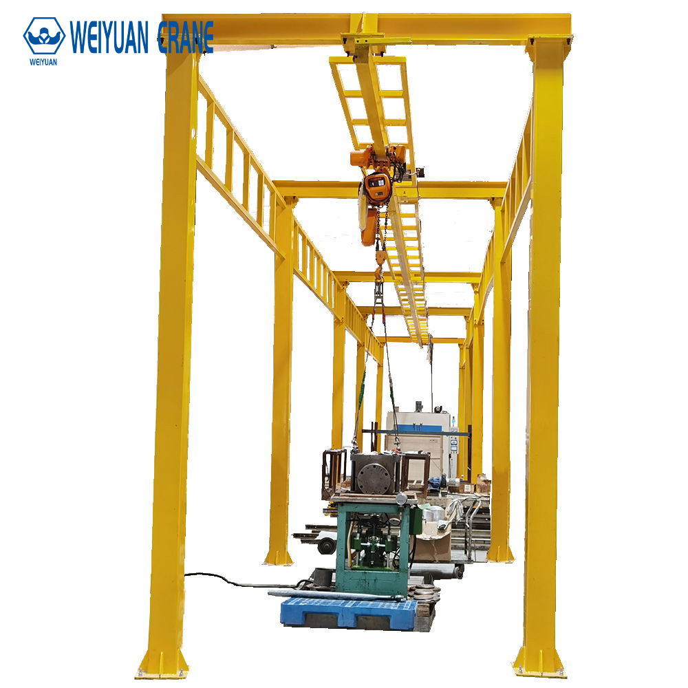
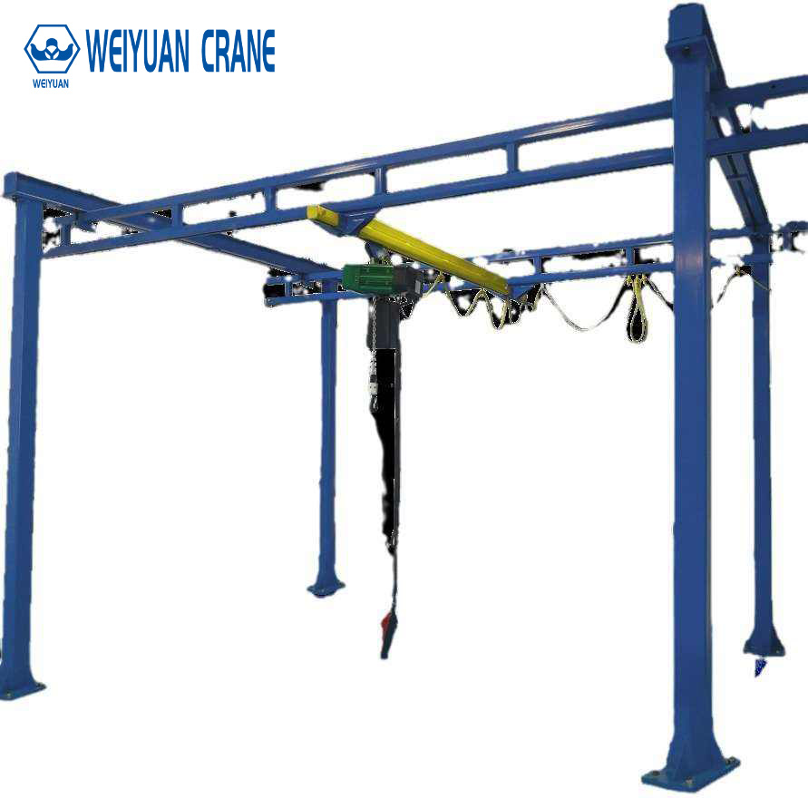
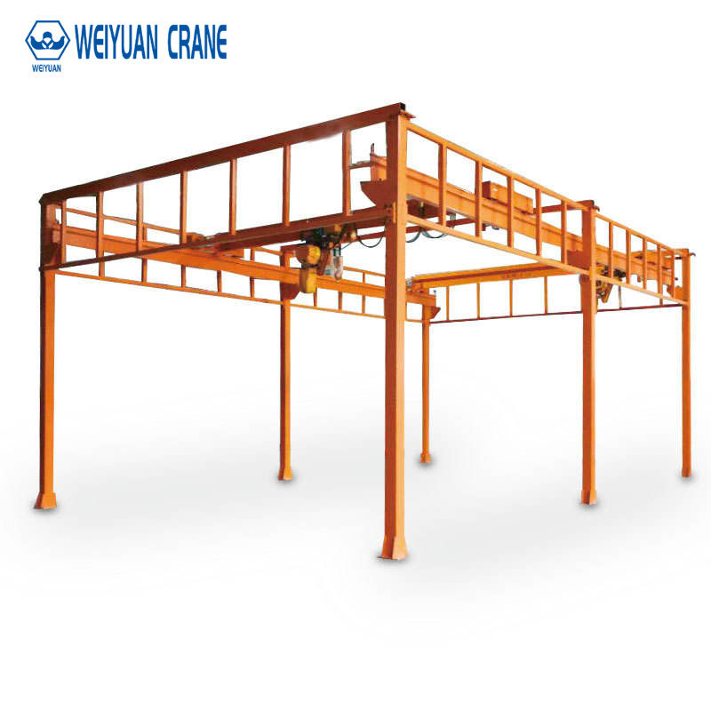
Part 3: Freestanding KBK Installation
When the building ceiling structure cannot carry the suspension loads, a freestanding support frame carries the KBK rails independently of the building.
Freestanding Frame Components
A standard KBK freestanding frame consists of:
- Vertical columns: Square or round steel tube columns anchored to the floor with base plates and anchor bolts
- Horizontal top beams: Connecting the column tops at the required rail elevation
- Bracing: Cross-bracing between columns for lateral stability against crane side forces and rail longitudinal forces
- Base plates and anchor bolts: Connecting the columns to the concrete floor
Foundation Requirements for Freestanding Frame
Each column base plate transmits vertical load (crane + rail dead load) and horizontal force (crane lateral and longitudinal forces) to the concrete floor through anchor bolts. The anchor bolts must be designed for these combined loads by a structural engineer.
Minimum concrete slab thickness for KBK freestanding installation: typically 150mm for light KBK systems (up to 500 kg) and 200 to 250mm for heavier systems (up to 2,000 kg). Verify with the structural engineer for the specific installation.
Installation Sequence for Freestanding Frame
Install anchor bolts at each column base position (use a template to ensure correct bolt pattern). Set column base plates over the anchor bolts and grout level. Allow grout to cure to specified strength before loading. Erect columns and tighten base plate nuts to specification. Install top horizontal beams connecting the column tops at the correct rail elevation. Install KBK rails on the top beams using the same suspension hardware as ceiling-mounted systems. Level and align rails as described in Phase 4 above.
Part 4: Integration with Automated Production Lines
KBK systems are increasingly integrated with automated production equipment — robotic assembly cells, automated conveyor systems, and warehouse management systems. Integration adds significant value but requires additional planning during the installation phase.
Sensor-Based Positioning
For semi-automated or fully automated KBK operation, absolute position sensors must be installed on the runway and bridge travel axes. Options include:
- Barcode position strips mounted along the rail with barcode readers on the trolley: low cost, ±5mm accuracy
- Linear encoders with reading heads mounted on the trolley: medium cost, ±1mm accuracy
- Laser distance measurement: highest accuracy, suitable for precision automation applications
Position sensor installation must be planned before rail assembly — sensor brackets and cable routing must be accommodated in the rail layout from the beginning.
Interface with Production Control Systems
KBK crane controllers communicate with production control systems through standard industrial protocols: PROFINET, EtherNet/IP, or Modbus TCP. The crane manufacturer must provide the communication interface documentation (process data mapping, diagnostic data mapping, function block descriptions) for integration with the facility’s PLC or MES.
Automated work order dispatch — the production system sending the crane a destination position when a workpiece is ready for transfer — reduces operator involvement to exception handling and dramatically improves throughput consistency.
Safety Zone Integration
Automated KBK systems must integrate with the facility’s safety zone management to stop crane motion when personnel enter the crane’s working area. Laser scanner safety zones (Type 3 per IEC 61496) mounted at the crane bridge perimeter provide continuous monitoring of the area below the crane. When a person is detected in the protected zone, the safety system commands a controlled stop within the stopping distance calculated for the crane’s maximum travel speed and payload.
Part 5: Maintenance of KBK Systems
KBK systems are among the lowest-maintenance overhead crane systems available, but they do require regular inspection and lubrication to maintain performance and safety.
Pre-use visual inspection (before each shift): Visually check all visible rail sections for damage. Verify trolley wheels are on the rail. Verify hoist chain or rope has no visible damage. Test hoist upper limit switch with no load at slow speed.
Monthly lubrication: Apply a small amount of light machine oil to the trolley wheel bearings and the rail running surfaces. Do not over-lubricate — excess oil attracts debris and accelerates contamination of the running surface. For aluminum rails in cleanroom environments, use only approved lubricants compatible with the cleanroom classification.
Annual inspection: Inspect all rail joint bolts for correct torque. Inspect all suspension hanger connections for looseness. Inspect hoist chain or rope per ASME B30.16 rejection criteria. Test all limit switches and safety devices. Verify rail alignment (elevation and span) has not drifted from installation values. Document findings and corrective actions.
Frequently Asked Questions
Q: How long does KBK installation take?
A: A typical two-rail, single-bridge KBK workstation crane (10-meter runway, 4-meter span) takes 1 to 2 days for a two-person installation crew experienced with KBK systems. Freestanding frame installations add 0.5 to 1 day for frame assembly before rail installation. Electrical connection and commissioning add a half day. Total project time from delivery to first production lift: 2 to 3 days.
Q: Can I install a KBK system myself?
A: The mechanical assembly (rail, trolleys, bridge, hoist) can be completed by maintenance personnel following the manufacturer’s installation manual. The electrical connection (power supply to the crane, motor wiring, limit switch wiring) must be performed by a licensed electrician. Structural verification of the ceiling or floor for suspension or column anchor loads must be performed by a licensed structural engineer before installation begins.
Q: What tools are needed for KBK installation?
A: Standard hand tools cover most of the installation: metric socket set (M8 to M20), torque wrench, spirit level or laser level, tape measure, chalk line, stepladder or scissor lift for ceiling work. No welding equipment, cutting tools, or special fabrication equipment are required.