
Articulating Jib Crane Guide: How the Double-Joint Design Eliminates Blind Spots & Reaches Tight Spaces
Published by: [Your Brand] Engineering Team | Last Updated: March 2026 | Reading Time: 9 min
Introduction
Every standard jib crane — whether floor-mounted, wall-mounted, or mast-type — has the same structural limitation: a single rigid boom that sweeps a fixed-radius arc. Loads can be positioned anywhere along that arc and anywhere within the hoist’s lift range, but they cannot be positioned behind the mast, around a machine column, or inside a piece of equipment that the straight boom cannot reach.
In many workstations, this limitation is inconsequential. The arc covers the work area, and the dead zone behind the mast is unimportant because no work happens there. But in a significant and growing number of manufacturing applications — CNC machining cells where workpieces must be loaded directly into the spindle chuck, robot welding stations where the fixture is recessed inside guarding, assembly cells where a component must be positioned over a mounting post surrounded by adjacent fixtures — the standard jib crane’s blind spot is not a minor inconvenience. It is a workflow obstruction that forces operators to resort to manual handling or multi-person lifts for the critical part of the operation that the crane cannot serve.
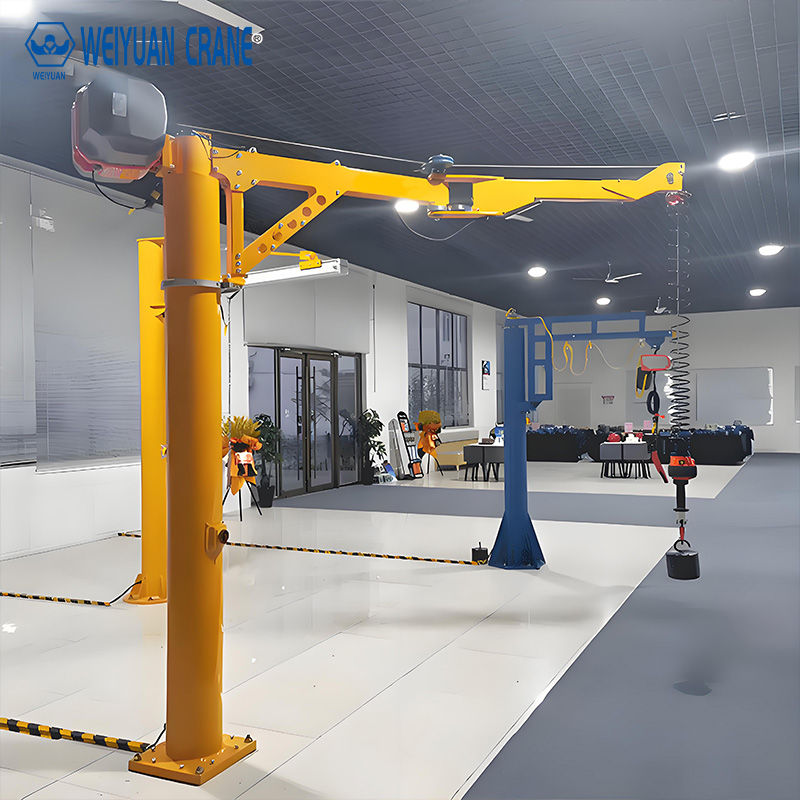
The articulating jib crane — a double-jointed design with two independently rotating arm segments connected by a knuckle pivot — solves this problem. The inner arm rotates around the main mast pivot (same as a standard jib); the outer arm rotates around the knuckle pivot at the end of the inner arm. The combination of two independent rotational degrees of freedom allows the hoist to reach positions that a single-arm design structurally cannot — including positions directly behind the mast, around machine columns, and deep inside equipment enclosures.
This guide provides the complete technical reference for articulating jib cranes: how the double-joint mechanism works and what it enables, the coverage geometry that distinguishes articulating from standard designs, the mounting configurations available, the applications where articulating cranes deliver unique value, how to specify an articulating jib crane correctly, and the maintenance considerations specific to the double-joint design.
Part 1: The Mechanics of the Double-Joint Design
How a Standard Jib Crane Covers Space
A standard single-arm jib crane generates a coverage area that is an annular sector — a pie-slice or full-circle shape centered on the mast, with the hoist accessible anywhere between the minimum and maximum reach along the boom and anywhere within the rotation arc.
The critical geometric feature of this coverage area is its dead zone: the area directly adjacent to and behind the mast where the boom cannot reach because the boom itself is attached there. For a floor-mounted pillar jib crane with 360-degree rotation and a 10-foot boom, the dead zone is a circle approximately 18 to 24 inches in radius around the mast — the area that no position of the straight boom can cover.
In most workstations, this dead zone is simply where the crane is mounted — not where work happens. But as workstations become more compact, equipment more closely spaced, and production cells more densely configured, the dead zone becomes an operational constraint.
How the Articulating Design Extends Coverage
An articulating jib crane adds a second pivot — the knuckle joint — at the end of the inner boom. The outer boom (the section beyond the knuckle) can rotate independently around this second pivot, adding a second degree of freedom to the hoist’s reachable positions.
The practical effect of this second degree of freedom is profound: the hoist can now reach positions that require folding the outer arm back toward the mast — reaching directly over the base, alongside the inner arm, or even slightly behind the mast position depending on the specific geometry and arm length ratio. The dead zone that is inherent in a straight-arm design is largely or completely eliminated.
More importantly for production applications, the articulating design allows the outer arm to reach around corners and obstacles. When a machine column, fixture post, or equipment housing blocks the direct path of a straight boom, the articulating crane can approach from a different angle — bending around the obstacle with its knuckle — and position the hoist exactly where it needs to be.
Coverage Geometry: Articulating vs Standard
Standard jib crane coverage (10-foot boom, 270-degree rotation):
- Coverage area: Annular sector with inner radius approximately 1.5 feet (mast diameter + minimum hoist approach) and outer radius 10 feet
- Dead zone behind mast: Significant — approximately the 90-degree sector blocked by the boom mounting structure
- Total accessible area: Approximately 235 square feet
Articulating jib crane coverage (5-foot inner arm + 5-foot outer arm, same total reach, 270-degree rotation):
- The knuckle pivot adds the ability to fold the outer arm back, covering the area near and behind the mast that the straight boom cannot reach
- When fully extended, the articulating crane covers a similar outer envelope to the straight boom at equivalent total arm length
- When the outer arm is folded at 90 degrees from the inner arm, the crane can reach positions 5 feet to the side of the mast — positions that are in the dead zone of the straight boom
- Total accessible area: Significantly larger than the straight boom equivalent, with no effective dead zone near the mast
The exact coverage geometry for any specific articulating crane depends on the inner-to-outer arm length ratio and the rotation limits of each pivot. Arm length ratios of 1:1 (equal inner and outer arm length) maximize flexibility; ratios of 2:1 (longer inner arm) maximize reach at the expense of near-zone coverage.
Part 2: Mounting Configurations for Articulating Jib Cranes
Articulating jib cranes are available in three primary mounting configurations, each with distinct advantages for specific workstation types.
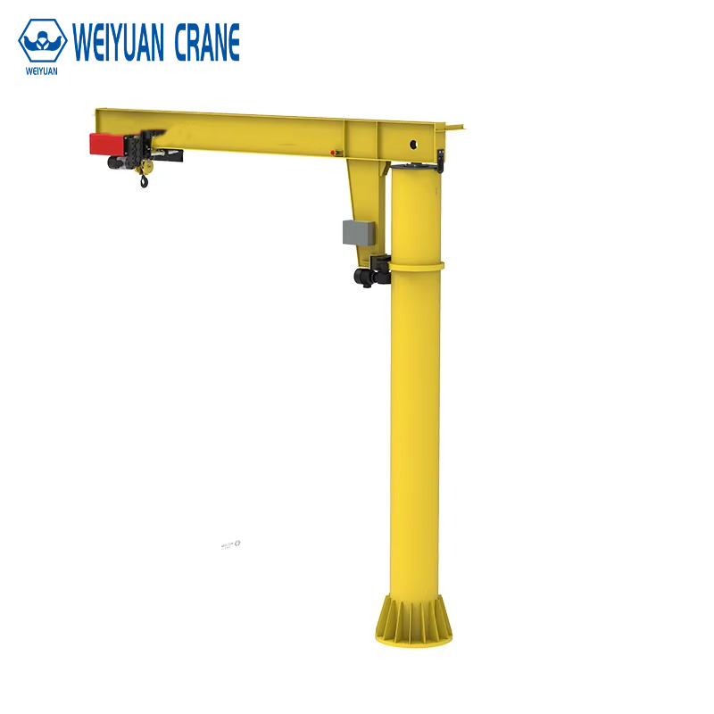
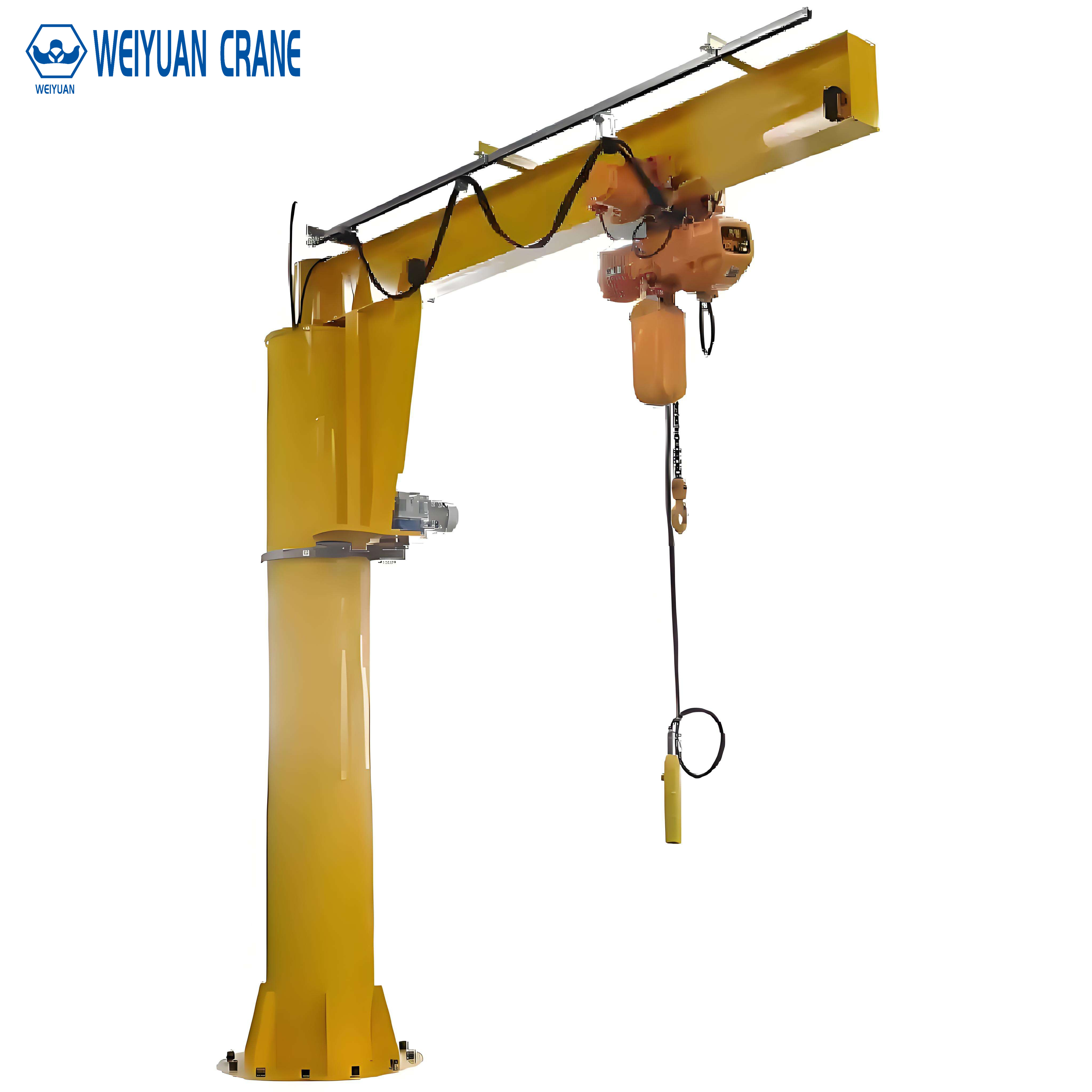
Floor-Mounted (Freestanding) Articulating Jib Crane
The mast is anchored to the floor through a base plate and anchor bolt system. The crane can be positioned anywhere on the production floor within reach of electrical supply and clear of obstructions.
360-degree rotation of the inner arm is possible with a floor-mounted design, providing maximum coverage. The outer arm’s knuckle adds additional reach around obstacles anywhere within the full rotation arc.
Best applications for floor-mounted articulating:
- CNC machining cell workpiece loading where the machine is accessible from multiple sides
- Assembly stations where work is performed on all sides of a rotating fixture
- Welding stations where the operator must work around the part from multiple positions
- Free-standing installations where no suitable wall or column exists within workstation reach
Foundation requirements: Similar to standard floor-mounted jib cranes — a concrete anchor meeting the manufacturer’s minimum depth and diameter specification. The articulating crane’s additional moment arm (created by the folded outer arm) means anchor loads can be slightly higher than equivalent straight-boom cranes; always obtain the specific foundation specification from the manufacturer.
Wall-Mounted Articulating Jib Crane
The inner arm mast is attached to a wall or column. Wall-mounted articulating cranes typically provide 180-degree rotation of the inner arm (limited by the wall surface) with full rotation of the outer arm around the knuckle pivot.
The critical advantage of wall-mounted articulating versus standard wall-mounted: the outer arm can fold toward and along the wall, accessing positions very close to the mounting surface that are completely inaccessible to a straight wall-mounted boom. For a workstation positioned against a wall with machine access from the wall side, this is operationally significant.
Best applications for wall-mounted articulating:
- Workstations positioned along a building wall where the operator works between the machine and the wall
- Equipment positioned close to a column where the straight boom would contact the column before reaching the required position
- Facilities where floor space for a freestanding mast is not available
Ceiling-Mounted (Track-Mounted) Articulating Jib Crane
The articulating arm assembly is suspended from an overhead track or carrier that travels along the ceiling. The crane provides the full coverage of the articulating arm over the entire length of the ceiling track — effectively combining the horizontal travel of a monorail with the reach flexibility of an articulating arm.
This is the most expensive but most coverage-efficient configuration for large production areas or long workstation runs. A single ceiling-mounted articulating crane on a 30-foot track can serve multiple adjacent workstations with the articulating arm reaching into each workstation cell.
Part 3: Applications Where Articulating Jib Cranes Deliver Unique Value
CNC Machining Cell Loading
Loading a horizontal machining center (HMC) requires positioning a workpiece — often a heavy casting or forging weighing 50 to 200 pounds — directly at the machine spindle or on the rotary pallet. The machine’s enclosure guarding means the only access point is through the enclosure door opening, and the machine spindle is set back 12 to 36 inches from the door.
A straight jib boom positioned outside the machine enclosure cannot reach straight back to the spindle position — the geometry requires the hoist to approach from outside, pass through the door opening, and then move laterally or rearward to the spindle position. A straight boom has no mechanism to make this lateral-inside-the-enclosure move. The operator must guide the load manually from the door opening to the spindle — with a heavy load at an awkward arm extension.
The articulating jib crane solves this precisely: the outer arm can fold to an angle that positions the hoist directly over the spindle centerline, then straighten as the hoist lowers the workpiece onto the fixture. The operator guides with minimal force rather than carrying or dragging the load.
Robot Welding Cell Component Loading
Automated welding cells use fixtures with multiple clamping and positioning elements that surround the weld zone. Loading a new component into the fixture requires placing it precisely in the fixture from above — but adjacent fixture elements and the robot arm’s working envelope restrict the approach path.
The articulating arm can approach from the optimal angle, using the knuckle to fold around the fixture elements that would block a straight-arm approach, and position the component directly over its locating pins for lowering.
Electrical Equipment Maintenance
Switchgear panels, transformers, and large electrical equipment require periodic maintenance that involves removing and reinstalling heavy components (switchgear drawout elements, transformer cores, motor generator sets) in confined equipment rooms. The equipment is often positioned against walls with other panels adjacent on both sides, leaving only a frontal approach path.
A ceiling-mounted articulating crane traversing the length of the equipment room — with the articulating arm reaching into the cabinet frontal access zone — provides the precision positioning that maintenance of this equipment requires without the multiple people and improvised rigging that alternative approaches demand.
Pharmaceutical and Cleanroom Applications
Stainless steel articulating jib cranes with IP65 protection and cleanroom-compatible surface finishes serve pharmaceutical filling and packaging lines where loads must be positioned into the filling machinery from the operator’s side — an approach that standard jib booms cannot serve because the filling equipment housing blocks the straight boom path.
Part 4: Specifying an Articulating Jib Crane — Key Decisions
Arm Length and Ratio
Total reach (inner arm + outer arm) determines the maximum horizontal distance from the mast to the hoist. This must be adequate to serve the full workstation reach requirement.
The inner-to-outer arm ratio determines the coverage flexibility. Equal arms (1:1 ratio) maximize the area near the mast that the folded outer arm can cover. A longer inner arm (2:1 ratio) maximizes total reach but reduces the ability to fold back near the mast.
For most production applications, an arm ratio of 1:1 to 1.5:1 (inner:outer) provides the best balance of total reach and near-zone coverage.
Capacity
Rated capacity for an articulating crane must account for the worst-case loading condition — which occurs when the outer arm is fully extended and the hoist is at the outer tip of the outer arm. In this configuration, the moment arm from the mast pivot to the hoist is equal to the full total arm length, creating the maximum structural demand on the crane.
Some articulating crane designs provide reduced capacity when the outer arm is fully extended beyond a certain angle relative to the inner arm — always verify the rated capacity diagram (load vs outer arm position) with the manufacturer.
Rotation Limits and Stops
The inner arm rotation range (typically 270 degrees for wall-mounted, 360 degrees for freestanding) and the outer arm rotation range around the knuckle (typically 270 to 360 degrees) define the full coverage envelope. Verify that the crane’s rotation limits allow the arm configuration needed for all required reach positions.
Travel stops — physical limit stops on both the inner arm pivot and the outer arm knuckle — must be set to prevent the crane from rotating into building elements, equipment, or personnel zones adjacent to the workstation.
Hoist Selection
The same hoist selection principles that apply to standard jib cranes apply to articulating designs. For production applications involving CNC loading and precision positioning, a VFD-controlled electric chain hoist providing continuously variable speed from near-zero to full speed is strongly recommended. The precision positioning advantage of the articulating arm geometry is only realized when the hoist also provides precision vertical positioning.
For ergonomic assist applications (loads 50 to 150 pounds where the intent is to reduce physical effort rather than mechanize the lift entirely), an intelligent assist system with load-sensing control transforms the articulating crane into an ergonomic tool that amplifies the operator’s natural movements.
Part 5: Maintenance Considerations Specific to Articulating Jib Cranes
The knuckle pivot at the end of the inner arm is the component unique to articulating designs and the one that requires specific maintenance attention:
Knuckle bearing lubrication: The knuckle pivot bearing must be lubricated at the same interval as the main mast slewing bearing — typically every 3 months under normal service. Access to the knuckle grease fitting is typically easier than the mast bearing; include it in the routine lubrication route.
Knuckle bearing play inspection: At each frequent inspection, attempt to rock the outer arm vertically and laterally at its tip. Excessive play (more than 1/4 inch of movement at the arm tip) indicates bearing wear requiring replacement. A loose knuckle bearing affects load positioning accuracy and, if neglected, can progress to structural instability.
Energy chain or festoon cable inspection: The electrical supply to the hoist must accommodate the movement of both the inner and outer arm. Energy chains and festoon systems at the knuckle experience more complex bending than those at a standard single-pivot jib. Inspect for kinking, cracking, and chafing at both the mast pivot and the knuckle pivot at every frequent inspection.
Rotation stop verification: Verify that both the inner arm and outer arm travel stops are secure and positioned correctly at each periodic inspection. Stops that have shifted from vibration or impact can allow the crane to rotate into adjacent equipment.
Frequently Asked Questions
Q: Can an articulating jib crane replace a standard jib crane for all applications?
A: Articulating jib cranes can serve all the applications that standard jib cranes serve, plus many that standard designs cannot. However, articulating cranes cost 40 to 80% more than equivalent-capacity straight boom designs. Where the workstation geometry does not require the near-zone reach or obstacle-avoidance capability of the articulating design, a standard jib crane delivers equivalent performance at lower cost. Use the articulating design where its unique coverage geometry is genuinely needed.
Q: What is the maximum capacity available for articulating jib cranes?
A: Most standard catalog articulating jib cranes are rated to 1 to 2 tons at full reach. Some manufacturers offer heavy-duty articulating designs to 3 to 5 tons. Beyond 5 tons, custom engineering is required. The structural challenge of the double-moment arm under full load limits practical capacity more than for straight-arm designs at equivalent arm length.
Q: How does a ceiling-mounted articulating crane differ from a standard monorail?
A: A standard monorail provides linear horizontal travel along the track and vertical hoist motion — two degrees of freedom. A ceiling-mounted articulating crane adds the rotational degrees of freedom of the articulating arm — the hoist can reach off the centerline of the track to either side, significantly expanding the coverage width beyond what a simple monorail can serve.