
Jib Crane for Aerospace & Aviation Maintenance: Engine Change, Component Handling & Clean Bay Specs
Introduction
Aircraft maintenance demands more from lifting equipment than almost any other industry. The components are irreplaceable. A single dropped part can write off an aircraft engine worth $5 million to $20 million. The access geometry is constrained by fuselage, wing, and nacelle structures that no standard jib crane configuration was designed around. And the regulatory framework — EASA Part-145 in Europe, FAA Part-145 in North America — imposes documentation and equipment certification requirements that standard industrial practice does not address.
Jib cranes in aviation MRO (Maintenance, Repair, and Overhaul) facilities are not catalog industrial products. They are specifically configured for engine removal and installation, landing gear handling, component workshop lifting, and clean bay operations — each with distinct specifications.
This guide explains the specific applications, the FOD (Foreign Object Damage) prevention requirements, the capacity and positioning specifications for engine handling, the clean bay environmental requirements, and the regulatory documentation that EASA and FAA Part-145 facilities require from their lifting equipment.
Part 1: Aviation MRO Application Categories
Engine Change — The Most Demanding Application
An aircraft engine change is one of the most complex lifting operations in any MRO facility. The engine is attached to the wing at three to four pylon attachment points. It weighs 1,500 to 12,000 kg depending on aircraft type. And it must be removed and installed while hanging from a three-axis engine stand that supports it at three points simultaneously.
The jib crane’s role in an engine change: positioning the engine stand and engine assembly during the final approach to the pylon attachment points, supporting the engine’s weight during the attachment sequence, and providing controlled lateral movement during the docking procedure.
Typical capacity requirements:
Narrowbody aircraft (CFM56, V2500, Leap): engine weights 2,300 to 3,600 kg. Engine stand: 600 to 900 kg. Total: 2,900 to 4,500 kg.
Widebody aircraft (GE90, Trent 800, GP7200): engine weights 7,500 to 9,000 kg. Engine stand: 1,500 to 2,000 kg. Total: 9,000 to 11,000 kg.
The crane’s rated capacity must cover the heaviest configuration — engine plus stand — with adequate margin. The CMAA duty class must reflect the actual cycle frequency of the engine shop.
Landing Gear Handling
Aircraft landing gear assemblies are heavy, complex mechanisms. Main gear assemblies on widebody aircraft weigh 1,500 to 3,500 kg. They must be precisely aligned during installation — the gear attachment pins must mate within ±1mm of the designed lug position.
Jib cranes serving landing gear bays must provide: adequate capacity for the gear assembly plus any fixtures used to support it, VFD micro-speed control for final approach positioning, and stability against the lateral forces that occur during pin installation.
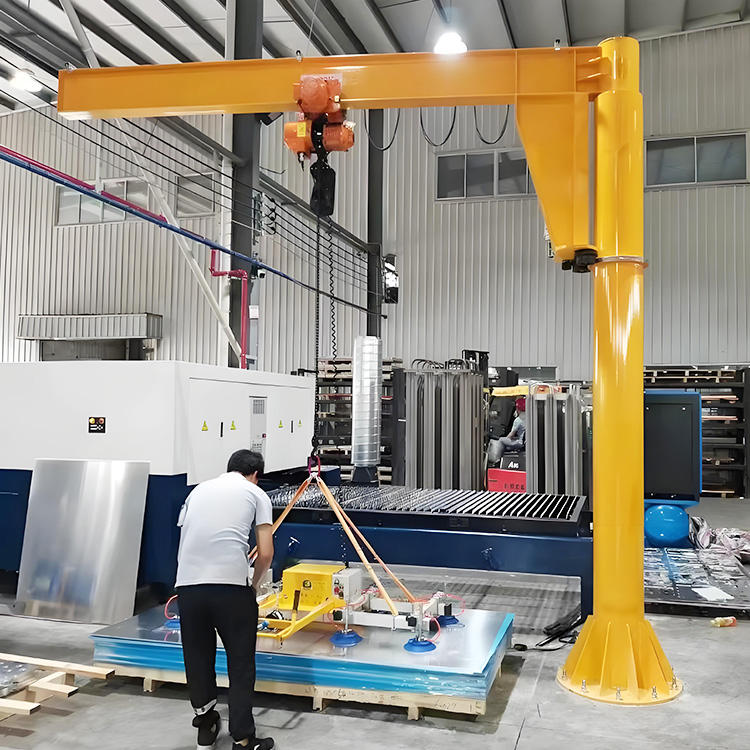
Component Workshop
Aircraft component workshops handle: APU (Auxiliary Power Unit) assemblies, hydraulic actuators, flight control surfaces, nacelle components, and avionic racks. These components range from 50 kg (avionic LRUs) to 1,500 kg (APU assemblies).
Workshop jib cranes serve individual workstations — the same function as general manufacturing jib cranes. The aviation-specific requirements: FOD prevention (no loose bolts or fasteners on the crane structure that could fall into a component), smooth controlled movement for delicate components, and compliance with the facility’s Part-145 maintenance organization exposition (MOE) requirements.
Part 2: FOD Prevention — The Aviation-Specific Safety Requirement
What FOD Is and Why It Matters in Crane Operations
Foreign Object Damage (FOD) is damage to aircraft systems caused by objects that should not be in the area. FOD causes billions of dollars of damage to the aviation industry annually. A single bolt left inside a fuel tank, an oil system, or an engine causes damage that may not appear until the aircraft is in flight.
Lifting equipment is a significant FOD source. Fasteners that work loose from overhead structures fall into open components below. Wire rope frays and leaves wire fragments. Chain links separate and leave metal debris.
Aviation MRO facilities apply strict FOD prevention programs to all equipment and tools in maintenance areas. Lifting equipment must comply with these programs.
FOD-Safe Crane Design Requirements
No loose fasteners on overhead structure: all crane fasteners must be either: fully torqued and safety-wired, retained by captive washers that prevent loss if the fastener loosens, or replaced with welded connections where mechanical fasteners are not required.
This requirement applies to: trolley wheel axle nuts, hoist suspension bolts, end stop bolts, limit switch mounting screws, cable gland lock rings, and any fastener within the overhead swing arc of the crane that could fall into an open aircraft component below.
No shedding lubricants: lubricant dripping from the hoist gearbox, drum, or rope falls into open components below. Specify: fully sealed gearbox (no vent, positive seal on all shafts), PFPE or sealed bearing greases that do not flow at operating temperatures, and drip pans under any component that contains liquid lubricant.
Wire rope inspection and replacement schedule: aviation MOEs typically specify wire rope inspection at every use (pre-shift visual check) and replacement on a calendar-based interval — typically every 12 to 24 months regardless of visible condition. The calendar-based replacement interval is more conservative than standard industrial ASME B30.16 criteria alone. It reflects the aviation industry’s preference for scheduled replacement over condition-based assessment for critical safety items.
Chain hoist chains: load chain in aviation applications must be: free of any visible contamination from lubricant or debris, inspected for foreign material trapped in the chain links before each use, and cleaned and inspected at each periodic maintenance interval.
Part 3: Engine Handling — Precision Positioning Requirements
Three-Point Engine Stand Coordination
Aircraft engines are handled on three-point slings or specialized engine stands that support the engine at its three or four attachment points. The stand must be level — the engine must not tilt relative to the pylon attachment interface.
During installation: the jib crane raises the engine-on-stand to the pylon height. The maintenance crew positions the assembly so the front and rear attachment pins align with the pylon lugs. The crane provides the vertical support while the crew applies lateral adjustments using the stand’s positioning screws.
The crane’s VFD micro-speed: the final approach to the attachment position uses micro-speed — typically 0.1 m/min or below — to allow the crew time to verify alignment at each attachment point without the crane moving away from position.
The crane’s load stability: during pin installation, the engine must remain stationary. Any swing or drift while the crew is working on the attachment pins creates a hazard. Specify: load brake in the hoist (prevents drift under static load), and anti-sway control (eliminates residual swing before the final approach).
Hook Height Requirement for Engine Access
The crane must reach above the engine pylon height with adequate clearance above the engine’s highest point to allow the lifting sling to clear the cowling during lowering.
For narrowbody aircraft (737, A320) engine changes in an MRO hangar:
Pylon height above hangar floor (with aircraft on jacks): typically 5.5 to 7.0 metres.
Engine maximum height above pylon: 0.8 to 1.2 metres.
Required minimum hook height: 6.3 to 8.2 metres.
Plus sling clearance above engine: minimum 0.5 metres.
Total required hook height: 6.8 to 8.7 metres.
This hook height requirement drives the selection of double-girder runway systems or elevated jib crane installations in many MRO hangars. Confirm the hook height calculation for the specific aircraft type before finalizing the crane specification.
Part 4: Clean Bay Specifications
What is a Clean Bay?
An aircraft clean bay — also called a controlled contamination area (CCA) or precision parts cleaning area — is a workspace where aircraft components are cleaned, inspected, and prepared for reassembly. The cleanliness requirements vary from general parts cleaning (ISO Class 8) to precision hydraulic component cleaning (ISO Class 5 or better).
Jib cranes serving clean bays must not introduce contamination into the controlled environment.
Particle Control Requirements
Metallic particles: trolley wheels running on steel flanges generate iron particles. In a clean bay, these particles fall onto cleaned components. Specify: polyurethane-coated wheels or enclosed track systems to minimize metallic particle generation.
Lubricant contamination: grease and oil from the hoist and trolley bearings can drip or mist onto components. Specify: sealed bearings throughout, PFPE lubricants (extremely low vapor pressure, no misting), and drip containment pans under all lubricant-containing components.
Paint particles: paint chips from the crane structure contaminate components. Specify: hard, chip-resistant coating system (epoxy-polyurethane at minimum 200 µm DFT), smooth surface finish without rough textures that shed particles, and annual inspection of the coating condition with spot repair of any damaged areas before they reach the chipping stage.
Airworthiness Directive Compliance
EASA and FAA Airworthiness Directives (ADs) applicable to specific aircraft types may specify requirements for the lifting equipment used during the AD compliance task. These requirements are task-specific and found in the AMM (Aircraft Maintenance Manual) or the AD itself.
Before specifying lifting equipment for AD compliance tasks: check the applicable AMM section and the AD for any stated lifting equipment requirements. Common requirements include: minimum rated capacity, required load test certification, prohibition on certain hoist types for specific components.
Part 5: Regulatory Documentation Requirements
EASA Part-145 Tooling Requirements
EASA Part-145 (Maintenance Organization Approvals) requires that maintenance organizations maintain and control all tools and equipment used in maintenance activities. For lifting equipment:
The organization’s MOE (Maintenance Organization Exposition) must document: the types of lifting equipment approved for use in the maintenance organization, the inspection and certification requirements for each type, the procedure for calibration and periodic load testing, and the records retention requirements.
Load test certification: EASA Part-145 facilities typically require lifting equipment to be load-tested at rated capacity annually, with a test certificate retained in the organization’s tooling calibration records. The test must be performed by a qualified person and the certificate must state: date, equipment identification, tested capacity, result, and tester’s qualification and signature.
FAA Part-145 Documentation
FAA AC 65-15A (Aviation Maintenance Technician Handbook) and the relevant FAA Part-145 regulations require that lifting equipment used on FAA-regulated aircraft be: suitable for the task (adequate capacity and configuration), maintained in serviceable condition, and identified and tracked in the organization’s calibration and maintenance records.
FAA Part-145 repair stations conducting heavy maintenance (C and D checks) are typically audited for lifting equipment documentation compliance. Inadequate records of load test certifications and periodic inspections are a common audit finding.
Required Documentation for Jib Crane Delivery to Aviation Facilities
When delivering a jib crane to an EASA Part-145 or FAA Part-145 facility, the documentation package must include:
Rated capacity plate (permanently affixed to the crane structure).
Design calculation summary confirming rated capacity at the applicable configuration.
Factory load test certificate (125% of rated capacity, witnessed by a qualified person).
CE Declaration of Conformity (for EASA Part-145 facilities in EU/EASA member states).
Wiring diagrams and maintenance manual with inspection intervals and lubrication schedule.
Spare parts list with manufacturer part numbers.
Part 6: 2026 Price Reference
Standard workshop jib crane (1-tonne, 4m boom, FOD-safe fasteners, sealed bearings, drip pan):
$5,500 to $12,000 installed.
Engine shop jib crane (3-tonne to 5-tonne, VFD, anti-sway, micro-speed 0.1 m/min, clean bay spec):
3-tonne, 5m boom: $22,000 to $48,000 installed.
5-tonne, 6m boom: $35,000 to $75,000 installed.
Wide-body engine change crane system (10-tonne to 12-tonne, double girder runway, VFD, anti-sway):
$120,000 to $280,000 complete system installed (runway + bridge + hoist + controls).
Aviation specification premium over standard industrial jib crane (FOD-safe + clean bay + PFPE + Part-145 documentation):
+35 to +55% on crane equipment price.
Frequently Asked Questions
Q: Can standard industrial wire rope be used in aircraft engine shops?
A: Technically yes — if it meets the applicable ASME B30.16 inspection criteria and the facility’s MOE does not specify a more restrictive standard. However, most aviation MRO quality systems specify calendar-based wire rope replacement (typically every 12 to 24 months regardless of condition) that is more conservative than ASME B30.16 criteria alone. Check the facility’s MOE tooling section for the applicable wire rope inspection and replacement standard before delivering a crane.
Q: Does the jib crane itself need to be EASA-approved?
A: No — jib cranes are not aviation articles under EASA or FAA regulations. They are industrial lifting equipment subject to machinery regulations (EU Machinery Directive, ASME standards). However, the maintenance organization using the crane in a Part-145 facility must: ensure the crane is suitable for the specific maintenance task, maintain it in serviceable condition, document its inspection and load test history, and ensure operators are trained in its use. The organization’s Quality Assurance function (not EASA or FAA) approves the crane as a controlled tool within the MOE framework.
Q: What is the minimum load test frequency required for aviation MRO lifting equipment?
A: EASA Part-145 and FAA Part-145 regulations do not specify a universal minimum test frequency for all lifting equipment. The organization’s MOE typically specifies annual load testing at rated capacity as the standard interval for overhead cranes and jib cranes. Some organizations apply 6-monthly testing for cranes used in personnel lifting or in high-consequence single-point-of-failure lifting tasks (specific AD compliance work). Check the MOE’s tooling control section for the organization’s specific interval requirement.