


Jib Crane Under Bridge Crane: How to Coordinate Two Lifting Systems in One Facility
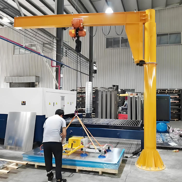
Introduction
Many facilities end up with two cranes sharing the same airspace, and it usually happens by accident. An overhead bridge crane serves the whole bay, then a workstation grows busy enough to need its own jib crane right underneath — a machine-loading point, a weld cell, a fitting station. Now two independent lifting systems occupy the same vertical space, and the moment they can both be in the same spot at the same time, you have a collision waiting to happen.
The problem is that each crane was specified on its own. The bridge crane sees the jib as just another obstruction under the runway; the jib sees the bridge as something that passes overhead unpredictably. Nobody designed the interaction — the clearance between them, who yields to whom, and what stops them from swinging into each other on a busy shift.
Here is how it plays out on the floor. One facility installs a jib under an existing bridge crane with no coordination, and within weeks the bridge operator clips the jib boom during a fast traverse — bending the boom, dropping a load, and grounding both cranes. Another facility maps the shared zone first, sets a hard vertical clearance, fits swing stops and travel limits, and runs both cranes through the same cell for years with no contact. Same two cranes. Same bay. The coordination decided the outcome.
This second article in the series shows you how to make two lifting systems share one facility safely. You will learn:
- Why coordinating two cranes is a distinct engineering problem, not two separate specifications.
- The clearance and duty parameters that govern a shared zone.
- The coordination configurations — zoning, interlocks, radio control, and operating rules.
- The space and clearance design that keeps the two systems apart.
- The common errors that cause collisions, plus 2026 budget figures.
Part 1: Why Coordinating Two Cranes Is Its Own Problem
Running a jib crane under a bridge crane is not two crane projects side by side. It is a single interaction problem, and it fails in ways that neither crane’s own design ever anticipates. Treat the two systems as independent and you get a facility where each crane is individually correct and the pair is unsafe.
The overlap zone belongs to neither standard alone. The bridge crane is governed by ASME B30.2; the jib crane by ASME B30.11. Each standard covers its own machine thoroughly, but the shared airspace — where the jib boom can rise into the bridge’s travel path — is not owned by either document on its own. You have to design that overlap deliberately, applying both standards together.
Two operators, two independent decisions. A bridge crane operator and a jib crane operator each control their own machine, often without seeing the other’s next move. Unlike a single crane where one person owns the airspace, here two people can commit to the same point at the same instant. Coordination has to remove that possibility mechanically or procedurally — you cannot rely on both operators looking up at the right second.
The motions are perpendicular and unpredictable. The bridge crane travels in straight lines along its runway; the jib sweeps a rotating arc. Where a straight travel path crosses a swinging arc, the point of closest approach shifts constantly with the jib’s boom angle. So what? A fixed “safe gap” that holds at one boom position can close to zero at another, which is exactly why the shared zone must be defined by the jib’s full swept volume, not a single snapshot.
Load swing adds a moving hazard neither crane fully controls. A suspended load on either crane swings during starts, stops, and travel. That swing extends each crane’s effective footprint beyond its structure, so two loads can touch even when the two cranes clear each other. The interaction envelope is bigger than the steel.
The practical takeaway: coordinating a jib under a bridge crane is a distinct discipline because the hazard lives in the shared space — between two standards, two operators, two motion types, and two swinging loads. Design the interaction, not just the two machines.
Part 2: Key Technical Parameters for a Shared Zone
Coordinating two cranes comes down to a defined set of numbers and rules. Get these right and the systems stay apart by design; miss one and you rely on luck. Every parameter below is framed by ASME B30.2 for the bridge crane, ASME B30.11 for the jib, and the CMAA/FEM duty class that rates both for cycle count.
Crane-to-Crane Vertical Clearance
The single most important number is the vertical gap between the highest point of the jib system and the lowest point of the bridge system.
- Measure from the top of the jib at its highest working position — boom, hoist, trolley, and any lifted load raised to full height — to the underside of the bridge crane, including its lowest hook block position and structure.
- Maintain a minimum clearance of 300 to 600 mm through the full range of both cranes, per common industrial practice and the manufacturers’ data.
- So what? This gap must hold at the worst case — jib at full lift, bridge hook at its lowest — not at rest. If the numbers only clear when both cranes are parked, they do not clear.
Horizontal Overlap and Swept Volume
Clearance is three-dimensional, so the horizontal picture matters as much as the vertical.
- Map the jib’s full swept arc (its rotation radius plus load swing) against the bridge crane’s full travel and trolley range.
- Identify the overlap zone — the floor area and airspace both cranes can reach — because that is the only place a collision can occur.
- Size every clearance and control decision around this swept volume, not the cranes’ static positions.
Duty Class Coordination
Two cranes in one cell should be rated for how hard that cell works, together.
- Match both cranes’ CMAA/FEM duty class (light A–B through severe E–F) to the real combined cycle count of the shared station.
- A high-cycle cell means both cranes work often and cross the overlap zone frequently — which raises the collision exposure and demands more robust coordination controls.
- So what? Under-rating either crane’s duty on a busy shared cell wears it out early and increases the number of near-misses in the very zone you are trying to protect.
Load Swing Envelope
Both cranes’ loads swing, so both envelopes must be accounted for.
- Estimate the swing radius from travel and rotation speed; faster motion and longer suspension mean wider swing.
- Add the swing envelope to each crane’s structural footprint when defining the overlap zone.
- VFD control on both cranes shrinks this envelope by softening starts and stops (see Part 4).
The practical takeaway: define the worst-case vertical clearance (300–600 mm), map the horizontal swept volume where the two cranes overlap, match both duty classes to the shared cell’s real cycles, and include load swing in the envelope. These four inputs, checked against ASME B30.2 and B30.11, define a coordinated zone.
Part 3: Coordination Configurations
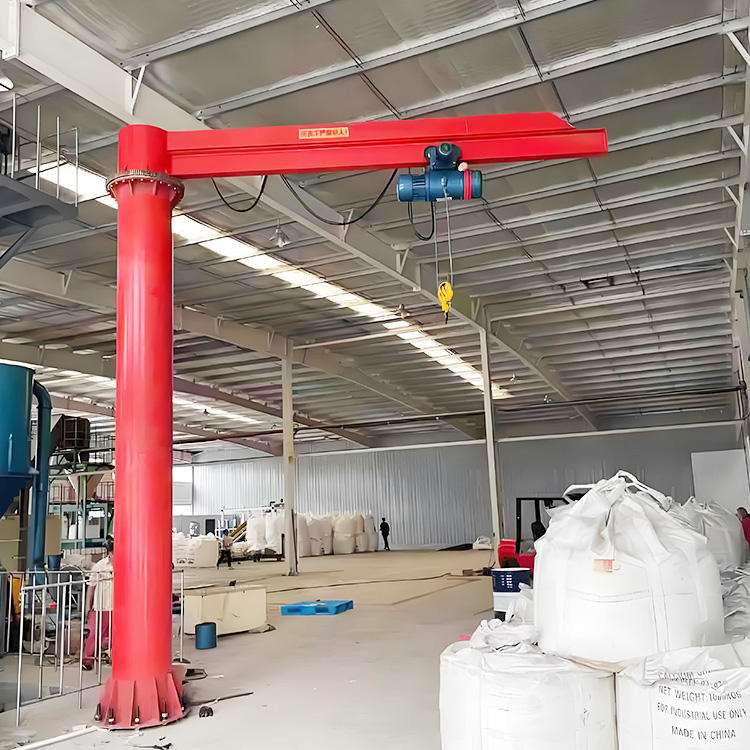
Once you know the overlap zone, you decide how to keep the two cranes out of each other’s way. The methods range from simple physical barriers to active electronic control, and most well-run facilities layer several. Here they are, from the most basic to the most sophisticated.
Physical Separation (Mechanical Stops)
The simplest and most reliable coordination is to make the collision physically impossible.
- How it works: mechanical swing stops limit the jib’s rotation so its boom never enters the bridge’s travel path, and bridge travel end stops keep the bridge out of the jib’s zone.
- Strengths: passive, fail-safe, and requires no operator decision — the steel simply cannot reach the conflict point.
- Best for: facilities where the jib’s useful arc does not actually need to overlap the bridge path, so a stop costs nothing in function.
- The limit: it only works when the two cranes can do their jobs without sharing the space. Where they must share it, you need active methods below.
Zoning (Defined Operating Areas)
Divide the shared airspace into zones and assign priority.
- How it works: the overlap zone is marked and governed by a rule — for example, the bridge crane always has right of way through the zone, and the jib must be clear (boom swung out, load lowered) before the bridge enters.
- Strengths: flexible, low cost, and keeps both cranes fully functional.
- Best for: facilities that need the shared space but can enforce a clear operating priority through training and signage.
- The limit: zoning is procedural, so it depends on operator discipline unless backed by interlocks.
Interlocks and Anti-Collision Sensors
Add electronics that stop a crane before it enters an occupied zone.
- How it works: proximity sensors, limit switches, or laser/radar anti-collision devices detect the other crane and automatically slow or stop travel or rotation before contact.
- Strengths: active protection that does not depend on the operator seeing the hazard; can enforce zoning automatically.
- Best for: busy, high-cycle cells where two cranes genuinely share the zone and human error is the main risk.
- The payoff: this is where procedural rules become mechanical certainty — the crane physically cannot cross into an occupied zone.
Radio Remote Control and Shared Visibility
Give operators control and sightlines that make coordination natural.
- How it works: radio remote control lets each operator move around the cell for the best view of both cranes, rather than being fixed in a cab or at a wall station. Clear signaling — lights, horns, or a shared spotter — announces intent.
- Strengths: better sightlines, faster reaction, and the ability to position for a clear view of the overlap zone.
- Best for: almost any shared cell, layered on top of stops, zoning, or interlocks.
- The limit: control and visibility reduce risk but do not remove it — pair radio control with a physical or electronic backstop.
The practical takeaway: use mechanical stops wherever the cranes do not truly need to share space, zoning where they do, interlocks and anti-collision sensors to make zoning fail-safe on busy cells, and radio control to give operators the sightlines to coordinate. The safest facilities layer these — a physical or electronic backstop behind every procedural rule.
Part 4: Space and Clearance Design
Coordination controls only work if the physical layout gives them room to work. A shared cell has to be designed as one three-dimensional space, with the vertical stack, the horizontal footprint, and the swing envelope all planned together. Get the geometry right and the controls in Part 3 have an easy job; get it wrong and no interlock can fully save it.
Design the Vertical Stack First
The relationship that governs everything is the vertical stack, from floor to roof.
- Work out the space budget top-down: bridge crane structure and its lowest hook position, the clearance gap (300–600 mm), then the jib’s highest point with a raised load.
- If the numbers do not clear, a low-headroom or ultra-low-headroom hoist on the jib recovers the height that makes the stack fit.
- Reader checkpoint: if the jib only clears the bridge with no load raised, the stack is too tight — the clearance must hold with the load at full lift.
Keep the Jib’s Arc Out of the Travel Lane
The cleanest layout is one where the two cranes rarely need the same spot.
- Position the jib column or wall mount so its useful working arc points away from the bridge’s main travel lane wherever possible.
- Use limited-swing (stop-limited) rotation to confine the boom to the arc the work actually needs, keeping it clear of the bridge path.
- This turns a shared-space problem into a mostly-separated one, which is always safer and cheaper.
Plan the Swing Envelope, Not Just the Structure
Design around where the loads go, not only where the steel goes.
- Add each crane’s load-swing envelope to its footprint when you lay out the overlap zone and set clearances.
- VFD control on both the jib and the bridge softens starts and stops, shrinking the swing envelope and letting loads place precisely without needing extra clearance.
- Less swing means a smaller overlap zone to protect — a real space and safety gain.
Leave Access and Maintenance Room
A shared cell still has to be inspected and serviced.
- Keep access for inspecting the jib’s rotation bearing, both hoists, and both brakes without one crane blocking the other.
- Plan a parking position for each crane that clears the overlap zone, so either can be locked out for maintenance while the other works.
The practical takeaway: design the vertical stack top-down with the clearance gap built in, aim the jib’s arc away from the bridge travel lane, plan around the load-swing envelope rather than the bare structure, and leave room to service both cranes. Good geometry makes the coordination controls easy; bad geometry makes them fragile.
Part 5: Common Errors and How to Prevent Them
Most dual-crane incidents trace back to a handful of coordination errors, and every one is preventable at the design stage. The pattern is consistent: each crane was specified correctly on its own, and the interaction between them was never designed. Here are the errors that cause collisions, and the fixes.
Error 1: Specifying the Two Cranes Independently
The jib and the bridge crane are each sized and installed correctly, but no one designs their interaction.
What goes wrong: each machine is individually compliant, yet the shared airspace has no defined clearance, priority, or backstop — so the first busy shift finds the conflict. Prevention: treat the pair as one system from the start, mapping the overlap zone and applying ASME B30.2 and B30.11 together before either crane is finalized.
Error 2: Clearance Checked Only at Rest
The vertical gap is confirmed with both cranes parked, not at their worst-case working positions.
What goes wrong: the jib at full lift with a raised load rises into the bridge’s lowest hook path, and the “adequate” clearance closes to nothing exactly when both cranes are working. Prevention: verify the 300–600 mm clearance at the worst case — jib at maximum lift, bridge hook at its lowest — through the full range of both machines.
Error 3: Relying on Operators to Watch for Each Other
Coordination rests entirely on two operators seeing and avoiding one another.
What goes wrong: two independent operators commit to the same point at the same instant, because neither can watch the other continuously while doing their own job. Prevention: back every procedural rule with a physical or electronic backstop — mechanical swing stops, travel limits, or anti-collision interlocks that make the collision impossible regardless of attention.
Error 4: Ignoring Load Swing in the Overlap Zone
The clearance is planned around the cranes’ steel, but not around their swinging loads.
What goes wrong: the two structures clear each other while the suspended loads swing into contact during starts and stops, dropping a load or damaging equipment. Prevention: include the load-swing envelope of both cranes in the overlap zone, and fit VFD control to soften motion and shrink the swing.
Error 5: Skipping Dual-System Commissioning and Documentation
Each crane is load-tested alone, but the coordinated system is never commissioned as a pair.
What goes wrong: the interlocks, zoning rules, and clearances are never verified working together, so a coordination fault stays hidden until an incident. Prevention: commission the cranes as a coordinated system — test the interlocks and stops, document the zoning and operating rules per ASME B30.2 and B30.11, and train both operators on the shared-zone procedure.
The practical takeaway: every dual-crane collision traces back to treating two cranes as two projects instead of one interaction. Design the shared zone, verify clearance at the worst case, back procedures with physical or electronic stops, account for load swing, and commission the pair together.
Part 6: 2026 Indicative Price Reference
Use these indicative 2026 figures to budget the coordination hardware and engineering for a shared jib-and-bridge cell. Actual costs vary with crane size, cell complexity, and the level of automation — but the relationships guide the decision, and the case for designing coordination in from the start is clear.
Coordination Hardware and Controls
| Item | Scope | Indicative 2026 cost (USD) |
|---|---|---|
| Mechanical swing stops (jib) | Rotation-limiting stops, installed | $300 – $1,500 |
| Bridge travel end stops / limits | Travel-limiting hardware | $400 – $2,500 |
| Proximity / limit-switch interlocks | Zone detection and auto-stop | $1,200 – $6,000 |
| Laser / radar anti-collision system | Active detection, slow-and-stop | $4,000 – $20,000 |
| Radio remote control (per crane) | Operator mobility and sightlines | $1,500 – $6,000 |
| VFD upgrade (per crane, per motion) | Soft motion, reduced swing | $1,800 – $7,500 |
Engineering and Commissioning
| Item | Scope | Indicative 2026 cost (USD) |
|---|---|---|
| Dual-system layout / clearance study | Overlap-zone mapping and clearance design | $1,500 – $8,000 |
| Structural verification (jib mount) | Engineering check for wall/pillar loads | $500 – $5,000 |
| Coordinated commissioning | Interlock test, load test, sign-off | $1,000 – $5,000 |
| Operator training (shared-zone procedure) | Both crews, documented | $500 – $2,500 |
Budget Notes
- The coordination study is the cheapest line and prevents the most expensive. A layout and clearance study costs a fraction of one boom-strike incident that grounds both cranes.
- Layer stops before sensors where you can. Mechanical stops are cheaper and fail-safe; reserve anti-collision electronics for cells that genuinely must share the zone.
- VFD earns its place on a shared cell. Softer motion shrinks the swing envelope and shrinks the overlap zone you have to protect — a safety and space return, not just smoother feel.
- Commission the pair, not the parts. Budget the coordinated commissioning as a distinct line; testing each crane alone does not prove the shared system is safe.

Frequently Asked Questions
Q: How much vertical clearance is needed between a jib crane and a bridge crane above it?
A: Maintain a minimum vertical clearance of roughly 300 to 600 mm between the highest point of the jib system and the lowest point of the bridge system, and — critically — verify that gap at the worst case rather than at rest. The worst case is the jib at its maximum working position (boom, hoist, trolley, and any lifted load raised to full height) measured against the bridge crane’s lowest point, which includes its hook block at its lowest travel position and the underside of its structure, not just the girder. The most common and dangerous mistake is confirming the clearance with both cranes parked, because a stack that clears at rest can close to zero the moment the jib lifts a load while the bridge hook is down. Check the clearance through the full range of both machines, and where the numbers are tight, fit a low-headroom or ultra-low-headroom hoist on the jib to recover the height that makes the vertical stack fit. Because this is a life-safety dimension governed by the interaction of ASME B30.2 and ASME B30.11, treat any position where the gap falls below the design minimum as a no-go condition, not a tolerance to be shaved.
Q: What is the best way to prevent a collision between two cranes sharing the same space?
A: The safest approach layers several methods rather than relying on any single one, and it always puts a physical or electronic backstop behind every procedural rule. Start with the cheapest and most reliable: mechanical stops — swing stops that limit the jib’s rotation so its boom never enters the bridge’s travel path, and travel end stops on the bridge — wherever the two cranes do not genuinely need to share the same airspace, because a stop the steel cannot pass is fail-safe and needs no operator decision. Where the cranes must share the zone, add zoning with a clear operating priority (for example, the bridge crane always has right of way and the jib must be clear before it enters) and make that zoning fail-safe with interlocks or laser/radar anti-collision sensors that automatically slow or stop a crane before it enters an occupied zone. Layer radio remote control on top so each operator can position for a clear view of the overlap zone and signal intent. The key principle is never to depend on two independent operators watching each other, because each is focused on their own machine and both can commit to the same point at the same instant — so the design must remove that possibility mechanically or electronically, not just procedurally.
Q: Do ASME B30.2 and B30.11 cover two cranes operating in the same area?
A: Each standard governs its own machine thoroughly — ASME B30.2 covers the overhead and gantry bridge crane, and ASME B30.11 covers the jib crane — including construction, installation, inspection, testing, and safe operation, so both must be satisfied for the two cranes individually. What neither standard owns exclusively is the shared airspace where the two systems overlap, which is exactly why coordinating them is its own engineering task: you apply both standards together and design the interaction deliberately on top of them. In practice that means defining the overlap zone from each crane’s full swept volume and load-swing envelope, setting and verifying the worst-case clearance, establishing operating rules and priority for the shared zone, and backing those rules with mechanical stops or anti-collision interlocks. It also means commissioning the pair as a coordinated system — not just load-testing each crane alone — verifying the interlocks and stops work together, documenting the zoning and operating procedure, and training both operators on the shared-zone rules. Treat the two standards as the floor for each machine and the coordinated design as the layer that makes the pair safe.