
Marine Jib Crane Guide: Shipyard, Offshore Platform & Vessel Deck Specifications
Introduction
A jib crane in a marine environment faces conditions that industrial specifications never anticipate. Salt-laden air attacks every unpainted surface within months. Wind loads that an onshore facility never experiences create dynamic forces that can exceed the static rated load. Platform motion on a floating offshore installation introduces accelerations that onshore structural design codes do not address.
A standard industrial jib crane installed at a shipyard, on an offshore platform, or on a vessel deck degrades rapidly. Corrosion breaches the paint system within 2 to 3 years. Electrical enclosures admit moisture. The structural steel begins section loss from inside out. In an offshore Zone 1 hazardous area, electrical failure becomes an explosion risk.
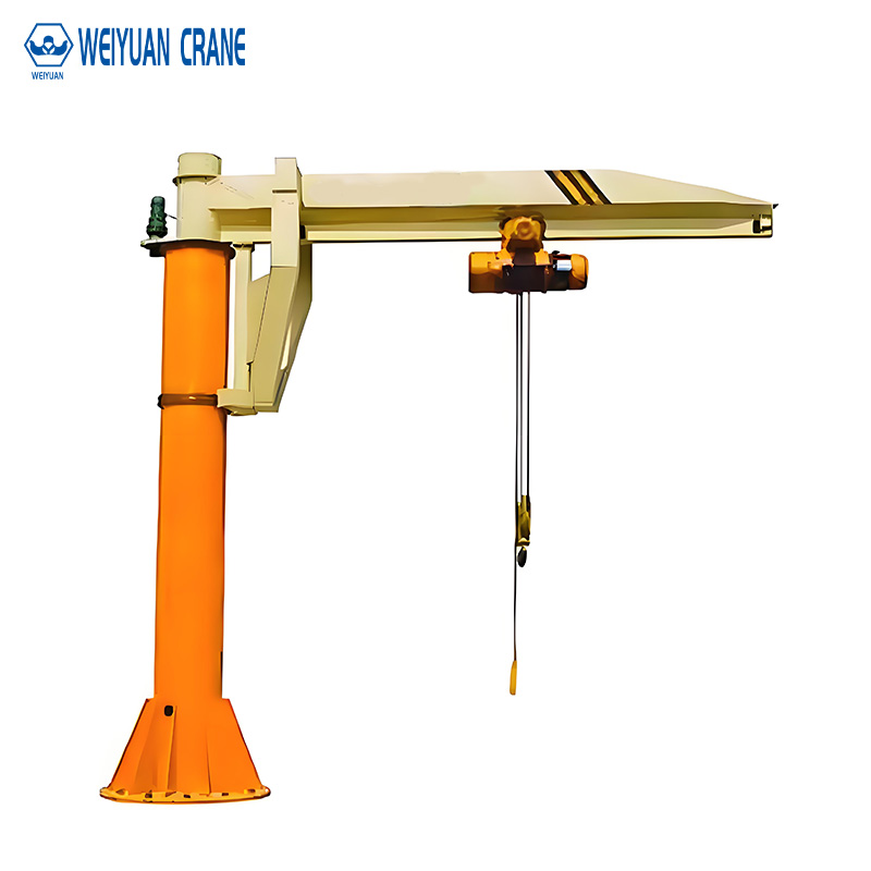
Marine jib cranes are not standard industrial cranes with a coat of marine paint. They are specifically engineered for corrosion resistance, dynamic loading, wind-induced load control, and regulatory compliance under maritime classification societies.
This guide provides the complete specification framework for jib cranes in shipyard, offshore platform, and vessel deck applications.
Part 1: Marine Application Categories
Category 1: Shipyard and Dry Dock
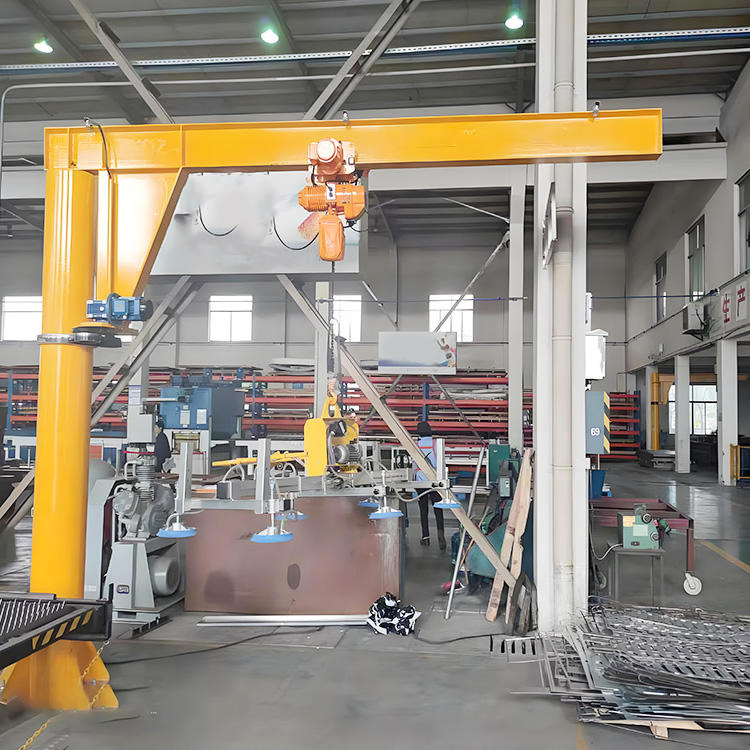
Shipyard jib cranes serve specific outfitting, maintenance, and repair tasks. Typical applications:
Component handling in the outfitting hall: installing piping systems, cable trays, HVAC units, and equipment modules into the vessel hull. Jib cranes serve individual workstations along the vessel sections.
Propeller and shaft handling in the dry dock: large naval and commercial vessels have propellers weighing 5 to 80 tonnes. Jib cranes at the stern dock positions handle propeller removal and installation during dry docking.
Deck equipment installation: winches, fairleads, bollards, and deck machinery are lifted into position during outfitting using deck-level or pier-mounted jib cranes.
Shipyard jib crane environment: coastal, outdoor, exposed to salt spray. ISO 12944 C5-M corrosion category. Operating temperature range −10°C to +45°C depending on location.
Category 2: Fixed Offshore Platform
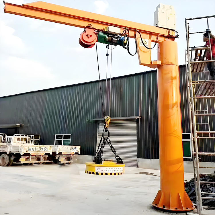
Fixed offshore platforms — oil and gas production platforms, wind turbine service platforms, jacket structures — use jib cranes for personnel basket transfers, equipment handling, and maintenance lifting on the platform deck.
The environment is more aggressive than a coastal shipyard. The platform is surrounded by seawater on all sides. Salt spray is continuous. High humidity is constant. Wave splash reaches deck equipment during storms. Corrosion category: CX (extreme marine per ISO 12944).
Additionally: oil and gas platforms have hydrocarbon processing equipment. The atmosphere in process areas and around well heads is classified ATEX Zone 1 or Zone 2. All crane electrical equipment must carry ATEX certification appropriate for the zone classification.
Category 3: Vessel Deck Installation
Jib cranes installed on vessel decks — cargo vessels, offshore supply vessels, research vessels, passenger ferries — handle deck cargo, equipment maintenance, and launch and recovery of small boats or scientific equipment.
The unique challenge of vessel deck installation: the crane is not on a fixed foundation. The vessel moves in all six degrees of freedom — roll, pitch, heave, surge, sway, and yaw. Every structural calculation must account for the dynamic accelerations that platform motion adds to the static crane loads.
Maritime classification society rules (Lloyd’s Register, Bureau Veritas, DNV, ABS) govern vessel deck crane design and installation. The crane must be designed, tested, and certified under the applicable class rules before the vessel’s flag state will accept it.
Part 2: Corrosion Protection — C5-M and CX Specifications
Why Standard Paint Systems Fail in Marine Environments
ISO 12944 C5-M (marine, very high corrosivity) and CX (extreme) describe the most aggressive corrosion environments in the industrial coating standard. Offshore platforms and vessel decks in tropical maritime climates fall in the CX category.
A standard C3 or C4 industrial coating system shows rust breakthrough at cut edges within 6 to 12 months in a CX environment. Complete coating failure follows within 2 to 4 years.
C5-M Full Specification
Surface preparation: Sa 2.5 to near-white blast. Profile depth: 50 to 70 µm Rz.
Coat 1 — Zinc-rich epoxy primer: 80 µm DFT minimum. The zinc content provides galvanic protection. If the primer is breached, the zinc corrodes preferentially, protecting the underlying steel.
Coat 2 — Epoxy intermediate coat: 100 µm DFT minimum. High-build barrier layer.
Coat 3 — Polyurethane or polysiloxane topcoat: 80 µm DFT minimum. UV-resistant, water-resistant, cleanable surface.
Total DFT: 260 µm minimum. Splash zone elements below 3 metres above mean waterline: 320 µm minimum.
CX Specification (Offshore Platforms in Tropical or Arctic Service)
Same primer and topcoat system with increased thicknesses:
Zinc-rich primer: 100 µm
Epoxy intermediate: 150 µm
Polyurethane topcoat: 100 µm
Total: 350 µm minimum.
Alternative CX protection: thermal spray zinc (TSZ) or thermal spray aluminum (TSA) applied to grit-blasted steel before painting. TSA provides galvanic protection for 20 to 30 years — significantly longer than paint-only systems. Required for submerged sections and splash zones on permanently installed offshore equipment.
Hardware Specification
All external fasteners: hot-dip galvanized (ISO 1461, 85 µm zinc) for C5-M. Type 316L stainless steel for CX environments.
Slewing bearing: marine-grade grease with calcium-complex or lithium-calcium base. Superior water resistance versus standard lithium-complex.
Electrical enclosures: IP66 minimum for C5-M. IP67 for CX offshore installations.
Part 3: Wind Load Design for Marine Jib Cranes
Design Wind Speed for Offshore Applications
Offshore platforms in the North Sea, Gulf of Mexico, and Asia-Pacific are designed for 50-year return period extreme wind events. Design wind speeds: 40 to 65 m/s depending on location and platform classification.
The jib crane is a component within this design envelope. The crane’s structural design must demonstrate survival under the platform’s design wind speed — in the out-of-service, parked condition with no load on the hook.
Operating wind speed limit: typically 15 to 20 m/s for offshore jib cranes. Above this limit: lower the load, rotate the boom to the minimum wind area position, and engage the boom locking device.
Storm parking position: most marine jib cranes have a defined storm parking position — typically with the boom pointed into the prevailing wind direction and secured by a mechanical locking pin or wire restraint. This position presents the minimum projected area to the wind.
Load Control in High Winds
Even within the operating wind speed limit, wind affects the suspended load. A 500 kg load presenting 0.5 m² of projected area to a 15 m/s wind receives approximately 70 N of horizontal wind force. This force creates load swing that complicates precision placement.
Dynamic braking: marine jib cranes specify dynamic braking on the hoist drive. When the hoist control is released during lowering, the dynamic brake decelerates the load smoothly — preventing the load from swinging in response to sudden brake application.
Tugger winch: for large or awkward loads in wind conditions, a tugger winch provides horizontal tension to control the load’s lateral position during lifting and lowering. The tugger winch runs a separate rope to the load and allows the rigger to control the load’s horizontal movement independently of the crane.
Part 4: ATEX Requirements for Offshore Platforms
Hazardous Area Zones on Offshore Oil and Gas Platforms
Oil and gas platform decks are classified under IEC 60079 / ATEX hazardous area standards. The classification determines the electrical equipment specification for every piece of equipment installed in the area.
Zone 1 (flammable atmosphere likely during normal operation): areas adjacent to wellheads, crude oil processing equipment, and gas compressor areas. Crane installations in Zone 1 require Category 2 equipment — Ex d (flameproof) or Ex e (increased safety) construction.
Zone 2 (flammable atmosphere only in abnormal conditions): areas surrounding Zone 1 processing equipment. Crane installations in Zone 2 require Category 3 equipment — Ex nA (non-sparking) construction minimum.
Non-hazardous (safe) areas: accommodation modules, control rooms, utility areas away from hydrocarbon processing.
Complete ATEX Specification for Zone 1 Marine Jib Crane
Hoist motor: Ex d IIB T4 Gb — flameproof, Group IIB (ethylene), Temperature class T4 (135°C maximum surface temperature), Equipment Protection Level Gb (Zone 1 capable).
Hoist contactor/VFD: Ex d or Ex e enclosure, same group and temperature class as the motor.
Limit switches: Ex d enclosure, IIB T4.
Pendant control: Ex d enclosure, IIB T4, marine-grade cable with strain relief.
Junction boxes and cable entries: Ex e enclosure, IIB T4. Cable glands must be certified Ex e for the cable type and size.
The complete crane assembly — not individual components — must be certified by a ATEX-recognized certification body (Intertek, SGS, Bureau Veritas, DNV). A crane assembled from individually certified components without system-level certification is not ATEX-compliant.
Part 5: DNV and Classification Society Certification
When Classification Society Certification Is Required
Maritime classification society certification (DNV, Lloyd’s Register, Bureau Veritas, ABS, ClassNK) is required for:
All lifting equipment permanently installed on classed vessels.
All lifting equipment on offshore installations registered under a flag state that requires class certification.
Lifting equipment used for personnel transfer (personnel baskets) on any installation — regardless of whether the installation itself is classed.
DNV Standard for Lifting Appliances
DNV-ST-0378 (Standard for Offshore and Marine Lifting Appliances) provides the technical requirements for offshore jib crane design, fabrication, testing, and certification.
Key DNV-ST-0378 requirements:
Structural design: the crane must be designed for the combined load case of rated load plus dynamic amplification factor plus wind load plus platform motion acceleration (for vessel deck installations).
Dynamic amplification factor for offshore cranes: 1.3 to 1.5 depending on water depth, sea state, and lifting operation type. This is significantly higher than the 1.15 used for standard industrial cranes.
Fatigue analysis: offshore cranes handling personnel require a formal fatigue analysis demonstrating adequate structural fatigue life under the operational load spectrum.
Factory acceptance testing (FAT): all offshore cranes must undergo FAT at the manufacturer’s facility before shipment. FAT includes: dimensional inspection, load test at 125% of safe working load (SWL), functional test of all controls and safety devices, witnessed by a DNV surveyor.
Certification document: the DNV surveyor issues a Certificate of Conformity after successful FAT. This certificate is the primary certification document required for installation on the vessel or offshore installation.
Part 6: Vessel Deck Mounting — Dynamic Load Considerations
Platform Motion Acceleration
A vessel at sea is not a stationary platform. Wave action causes the vessel to accelerate in all six degrees of freedom. These accelerations add to the crane’s static loads and must be included in the structural design.
Dynamic accelerations for jib crane structural design (from DNV-ST-0378):
Vertical (heave): 0.2g to 0.7g depending on vessel type and sea state design condition.
Horizontal (surge and sway): 0.1g to 0.4g.
Roll acceleration at the crane foundation: depends on the crane’s distance from the vessel’s roll center.
Combined load: the structural load at the crane’s foundation under rated load, design sea state, and design wind speed simultaneously.
For a 2-tonne jib crane on a supply vessel with 0.4g vertical acceleration:
Static vertical load: 2,000 kg × 9.81 = 19,620 N
Dynamic vertical load addition: 2,000 kg × 0.4g × 9.81 = 7,848 N
Total vertical design load: 27,468 N — 40% higher than static
The crane foundation and vessel deck structure must carry this combined design load. The vessel’s structural drawings must confirm the deck plating and framing below the crane foundation can carry the increased load.
Anti-Heeling Provisions
On offshore supply vessels and anchor handling vessels: loading operations frequently change the vessel’s weight distribution. The vessel may list (heel) up to 5 to 10 degrees during cargo loading.
Jib cranes on these vessels must be designed for operation at the maximum design list angle. The structural overturning calculation must account for the additional moment created by the list angle acting on the crane’s weight and load.
Part 7: 2026 Price Reference
Marine jib crane (C5-M coating, IP66, stainless hardware, without ATEX):
1-tonne, 4m boom, coastal shipyard specification: $8,000 to $18,000
3-tonne, 5m boom, coastal shipyard: $18,000 to $40,000
5-tonne, 6m boom, coastal shipyard: $32,000 to $70,000
ATEX Zone 1 offshore platform jib crane (Ex d IIB T4, CX coating, IP67):
1-tonne, 3m boom: $25,000 to $55,000
3-tonne, 4m boom: $45,000 to $95,000
DNV-certified vessel deck jib crane (dynamic load analysis, FAT, certification):
2-tonne, 4m boom: $35,000 to $75,000
5-tonne, 6m boom: $80,000 to $175,000
DNV/ATEX combined specification (offshore oil and gas platform):
3-tonne, 4m boom: $75,000 to $160,000
The marine premium over standard industrial specification: C5-M adds 40 to 60%. ATEX Zone 1 adds 80 to 150%. DNV certification adds 20 to 40% over base marine specification.
Frequently Asked Questions
Q: Can a standard CE-marked industrial jib crane be used on a vessel deck if it is painted with marine paint?
A: No. CE marking under the EU Machinery Directive addresses mechanical safety for normal industrial use conditions. It does not address: dynamic loading from vessel motion, survival under offshore design wind speeds, or maritime classification society structural requirements. A CE-marked crane on a vessel deck is not compliant with SOLAS (Safety of Life at Sea) requirements for vessel lifting equipment. Maritime classification society certification is required for vessel deck installations.
Q: Is DNV-ST-0378 the only standard applicable to offshore jib cranes?
A: DNV-ST-0378 is the DNV standard. Other classification societies have equivalent standards: Lloyd’s Register ShipRight Design and Construction (D&C) rules, Bureau Veritas NR526 (Rules for the Design and Testing of Lifting Appliances), ABS Guide for Certification of Lifting Appliances. All cover essentially the same technical ground — dynamic load analysis, fatigue, factory acceptance testing — but with specific formatting and procedural differences. If the vessel or platform is classed by a specific society, use that society’s applicable standard.
Q: How frequently must marine jib cranes be inspected?
A: Under DNV and most classification society rules: thorough examination by an approved surveyor at intervals not exceeding 12 months for cranes used in normal cargo operations, and 6 months for cranes used in personnel lifting operations. In addition: the crane operator or an appointed competent person must perform a visual inspection before each use and a more detailed inspection monthly. The 12-month and 6-month thorough examinations require a functional load test at the Safe Working Load (SWL). These records must be maintained in the crane’s certificate file on board the vessel or platform.