


Overhead Crane Column & Building Frame Design: Wheel Loads, Crane Columns, and Lateral Bracing Requirements
Introduction
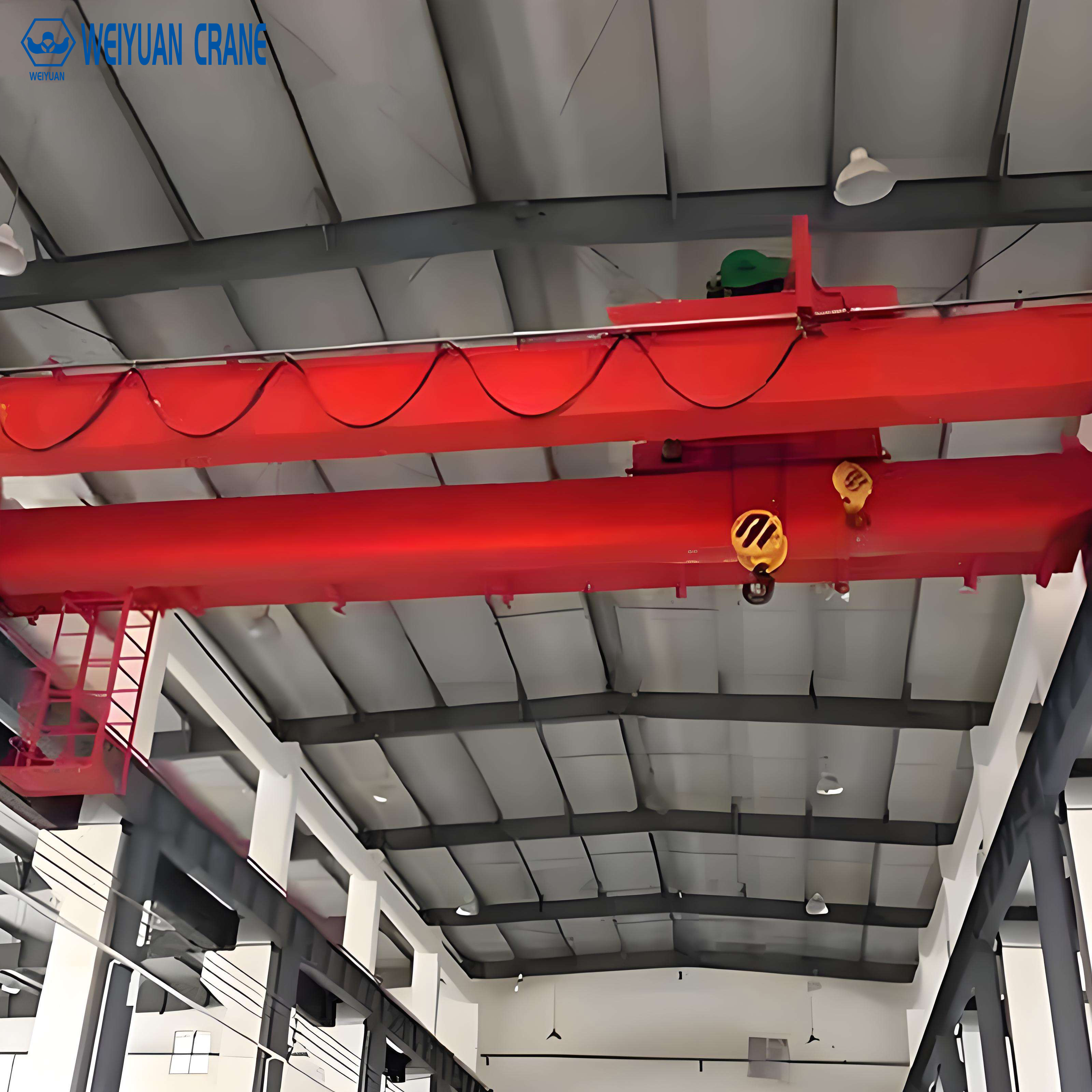
A fabrication plant I reviewed had done almost everything right. The crane was correctly specified — a 30-tonne double-girder top running unit, the configuration work from the first three articles in this series handled properly. The runway beams were deep, capped, and detailed for fatigue. The engineer who designed the runway was competent, and it showed. Then the whole thing started leaning.
Not the crane. Not the runway. The columns. Within three years of commissioning, the crane columns had drifted visibly out of plumb, the runway rails had opened up out of gauge at the top, and the crane skewed worse every month. The maintenance team kept re-aligning the rails, and the rails kept drifting back. The problem wasn’t anything they could fix at rail level, because it wasn’t at rail level. The building frame had been designed for the roof and the wind — but nobody had run the crane’s lateral thrust and the eccentric wheel loads through the columns properly. The columns were strong enough to stand up. They were nowhere near stiff enough to hold a crane runway in line.
That’s the pattern with crane building frames. The crane gets the attention, the runway beam gets some attention, and the columns — which carry everything into the foundation and hold the entire runway in alignment — get designed as if they were ordinary building columns with a crane bolted on as an afterthought. A crane column isn’t an ordinary column. It carries a heavy vertical load applied off its centerline, it fights lateral thrust on every pass, and it has to stay stiff enough that the runway it supports never drifts out of tolerance. Get the frame right and the runway stays true for thirty years. Get it wrong and no amount of rail re-alignment will save you — you’re fighting the building itself.
This is the fourth article in our overhead crane building structure series, following Top Running vs Under Running, Single vs Double Girder, and Runway Beam Design. Here we cover the frame that carries it all: the columns and the bracing.
What you’ll take away:
- Why crane wheel loads behave nothing like standard building loads
- How to design a column for combined crane and building loads applied eccentrically
- When to use a stepped column and when a separate crane column wins
- The lateral bracing — knee braces, tie rods, roof interaction — that keeps the runway in line
- Longitudinal bracing and the crane stop/buffer forces most frames forget
- A checklist referencing CMAA Spec No. 70 and AISC Design Guide 7
- 2026 cost benchmarks so the frame steel doesn’t ambush your budget
Part 1: Why Crane Wheel Loads Aren’t Standard Building Loads
The first mistake in crane frame design is treating crane loads as just more weight for the columns to carry. They aren’t. A crane loads a building in ways ordinary roof and floor loads never do, and each difference drives a specific design demand.
Four Ways Crane Loads Are Different
- They move. A crane’s wheel loads travel along the runway and across the bridge, so the peak load appears at different points on the frame at different times. The column sees maximum load only when the crane is parked near it with the trolley run to that side — a position the engineer has to hunt for, not assume.
- They’re dynamic. A crane snatching a load off the floor applies more than its static weight. Codes add an impact factor — commonly 15 to 25% for electric hoists per CMAA — on top of the static wheel load, and that amplified load runs straight into the column.
- They’re eccentric. On a stepped or bracketed column, the crane load lands on a bracket or a step offset from the column’s centerline. That offset turns a vertical load into a vertical load plus a bending moment on the column — the effect the fabrication plant’s frame never accounted for.
- They’re lateral and longitudinal, not just vertical. The crane pushes sideways when the trolley accelerates and brakes (lateral thrust), and along the runway when the bridge starts and stops (longitudinal thrust). Ordinary building columns rarely see forces like these applied repeatedly at runway height.
The Load Path Into the Frame
   CRANE LOAD PATH INTO THE FRAME

        [ bridge + load + impact ]
                 ↓
         [ end truck wheels ]
                 ↓
   ═══════════════════════════   ← runway beam
                 ↓  (offset e)
              ┌──┴──┐
              │bracket│  ← eccentric load = P + (P × e) moment
              │     │
              │ COL │  ← column: axial + bending + lateral thrust
              │     │
             ═╧═════╧═   ← base + foundation
Every one of those forces — amplified, eccentric, and multi-directional — arrives at the column and has to travel down to the foundation without the column overstressing or deflecting too far. That second part, deflection, is what catches most frames out.
Section summary: crane loads move, amplify, land off-center, and push sideways. Design the column for the worst crane position with impact, eccentricity, and thrust all applied together — not for a static weight sitting on the centerline.
Part 2: Column Design Under Combined Crane and Building Loads
A crane building column does two jobs at once: it carries the roof and wall loads any building column carries, and it carries the crane’s vertical, lateral, and longitudinal forces at runway height. The two load systems combine, and the column has to be designed for the combination — not for each in isolation.
The Column Is a Beam-Column
Because the crane load arrives eccentrically (Part 1), the column carries axial compression and bending at the same time. Engineers call this a beam-column, and it’s a fundamentally harder design case than pure compression. The column has to satisfy an interaction check — the combined effect of axial load and bending moment together must stay within the section’s capacity, per the AISC interaction equations.
Add the load combinations codes require — crane plus dead plus roof live plus wind, in the various patterns that produce the worst case — and the governing condition is rarely obvious by inspection. It has to be calculated.
Strength Isn’t the Hard Part — Drift Is
Here’s what the fabrication plant missed. A column strong enough to carry the combined loads can still be far too flexible to hold the runway in alignment. The lateral thrust from the crane pushes the top of the column sideways, and if the column deflects too much, the runway drifts out of gauge and the crane skews — exactly the failure that no rail re-alignment could cure.
Crane building codes therefore impose a lateral drift limit at the runway level, separate from and stricter than ordinary building drift limits. A common target holds the sidesway deflection at the crane rail to something on the order of H/240 or tighter (and stricter still for high-duty cranes), where H is the height to the runway. Meeting that drift limit — not just the strength check — is usually what governs the column size on a crane building.
| Design check | What it controls | Why it matters |
|---|---|---|
| Axial + bending interaction | Column strength under combined load | Column must not overstress or buckle |
| Lateral drift at rail level | Sideways stiffness of the frame | Keeps runway in gauge; prevents skew |
| Fatigue at bracket connection | Cyclic load at the crane bracket | Connection survives the duty cycles |
| Base and anchor design | Load into the foundation | Transfers axial, moment, and shear to ground |
Section summary: a crane column is a beam-column carrying combined, eccentric, cyclic loads — and it’s usually sized by drift, not strength. Design it to the interaction equations and the lateral drift limit at rail level, or the runway won’t stay in line.
Part 3: Stepped Columns vs Separate Crane Columns
Once you accept the column carries both building and crane loads, the next decision is how to arrange it. Two configurations dominate, and the choice turns on crane capacity, building height, and how much the crane load dwarfs the roof load.
The Stepped Column
A stepped column is a single column with two segments: a heavier lower section that carries the crane runway on a step (a bracket or a change in section), and a lighter upper section that continues up to carry the roof. The crane load lands on the step; the roof load continues down the upper shaft and combines with the crane load in the lower shaft.
   STEPPED COLUMN

        ┌──┐   ← upper shaft (roof load)
        │  │
        │  │
     ┌──┴──┴──┐  ← STEP: runway lands here
     │ crane  │
     │ runway │
     │ bracket│
     │        │   ← lower shaft (crane + roof, heavier)
     │        │
    ═╧════════╧═  ← base
Where it fits: the common, economical choice for most single-building crane bays, where the crane and building share one integrated frame. The step places the runway load close to the column centerline, keeping the eccentric moment manageable, and one column does both jobs.
The Separate Crane Column
Here the crane runway is carried on its own dedicated column, structurally distinct from the building column (though often standing right beside it, sometimes laced together). The crane column takes the crane loads straight to its own foundation; the building column carries only the roof and walls.
   SEPARATE CRANE COLUMN

     ┌──┐        ┌──┐
     │  │        │  │  ← building column (roof only)
     │  │  ┌───┐ │  │
     │  │  │run│ │  │  ← crane column carries runway
     │  │  │way│ │  │     to its own base
     │  │  │   │ │  │
    ═╧══╧══╧═══╧═╧══╧═  ← separate bases
Where it fits: very heavy cranes, tall buildings, or cases where the crane loads so dominate that combining them with the building frame would drive an uneconomical stepped column — or where a crane is added to an existing building whose columns can’t take the extra load. Isolating the crane loads keeps them out of the building frame entirely.
Choosing Between Them
| Factor | Stepped column | Separate crane column |
|---|---|---|
| Crane capacity | Light to heavy (most bays) | Very heavy / dominant crane loads |
| Building height | Low to moderate | Tall, or crane load governs |
| Steel efficiency | Better when loads are shared | Better when crane load dwarfs roof |
| Retrofit to existing building | Difficult | Often the only option |
| Foundation | One (combined) | Separate crane foundation |
Section summary: default to the stepped column for an integrated crane bay — it’s the economical norm. Move to a separate crane column when the crane load dominates the building load, the building is tall, or you’re adding a crane to a frame that can’t carry it.
Part 4: Lateral Bracing — Knee Braces, Tie Rods, and Roof Interaction
Column size alone doesn’t control lateral drift. The frame needs a defined system to resist the crane’s side thrust and carry it safely to the foundation — and this is precisely the system the fabrication plant’s building lacked. Without it, the columns were left to cantilever against the thrust on their own, and they couldn’t hold the line.
Where the Lateral Thrust Goes
The crane’s lateral thrust is applied at runway height, sideways, on every trolley acceleration and stop. The frame has to catch that force at the runway, spread it into the building’s structural system, and deliver it to the ground — all while keeping the runway-level drift within limit. Three elements do this work.
Knee Braces
A knee brace is a diagonal member connecting the column to the roof beam or truss, stiffening the joint between them. It braces the top of the column against sidesway, dramatically increasing the frame’s lateral stiffness at runway level.
   KNEE BRACE

   roof beam ═══════════════
              ╲
               ╲  ← knee brace (diagonal)
                ╲
     ┌──┐        ╲
     │  │─────────┘
     │COL│
     │  │
The trade-off: the knee brace projects into the corner of the bay, reducing clearance near the top of the column. On a crane building this can clash with the crane’s end approach or the hook’s reach into the corner — so the brace geometry has to be coordinated with the crane’s clearance envelope.
Tie Rods and Horizontal Bracing
Where knee braces intrude too far, or the thrust is large, horizontal bracing at runway level — tie rods or a horizontal truss running between frames — ties the runway beams back to points of stiffness and shares the thrust across multiple frames rather than loading one column alone. This is the same tie-back principle used to brace the runway beam’s top flange, extended into the building frame.
Roof Structure Interaction
In a rigid-frame building, the roof beam and columns act together as a moment frame — the rigid joints between them resist sidesway without a separate diagonal brace. This works, but it demands stiffer, moment-connected joints and usually heavier members, and the frame’s drift under crane thrust must still be checked against the runway limit. The key point: the roof structure is part of the crane’s lateral system, not a separate roof sitting on top. Design them together, or the crane thrust finds the weak link.
Section summary: the columns need a defined lateral system — knee braces, tie rods, or moment-frame action — to catch the crane’s side thrust and hold the runway in line. Coordinate the bracing geometry with the crane’s clearance envelope, and design the roof and columns as one lateral system.
Part 5: Longitudinal Bracing and Crane Stop/Buffer Forces
Lateral bracing handles the sideways thrust across the bay. But the crane also pushes along the runway — when the bridge accelerates, brakes, and above all when it runs into the end stops. This longitudinal direction is the one crane frames most often neglect, and it carries one of the largest single forces in the whole design.
Longitudinal Thrust in Normal Running
Every time the bridge starts or stops, it drives a longitudinal force along the runway — commonly taken as a fraction of the crane’s weight per CMAA. That force has to be carried down to the foundation somewhere along the runway length, and it can’t be left to the columns bending the weak way.
The standard solution is a longitudinal bracing bent — a braced panel (diagonal bracing between two columns) at one point along each runway line, sized to take the accumulated longitudinal thrust and deliver it to the ground.
   LONGITUDINAL BRACING BENT (elevation along runway)

   ═══════════════════════════════  ← runway beam
     │      ╲      ╱      │
     │       ╲    ╱       │
     │        ╲  ╱        │   ← diagonal bracing
     │         ╲╱         │      (takes longitudinal thrust)
     │         ╱╲         │
     │        ╱  ╲        │
    ═╧═══════╧════╧═══════╧═  ← bases
The Buffer Force — The One People Forget
Here’s the force that surprises people. When a crane runs to the end of its runway, it strikes the end stops through buffers — energy-absorbing devices that decelerate the crane. Even with buffers, the collision force transmitted into the end stop and the frame behind it can be very large, and it acts longitudinally, straight into the structure at the runway end.
The end stop, its connection to the runway beam, and the bracing that carries the force to ground all have to be designed for this buffer impact — a specific load case in CMAA and the building codes. Skip it and a crane that over-travels (a control fault, an operator error) can tear the end stop off, damage the runway, or drive the crane off the end — a genuine catastrophic failure mode, not just a maintenance issue.
Section summary: the crane pushes along the runway too. Provide a longitudinal bracing bent to carry normal longitudinal thrust, and design the end stops and their supporting structure for the buffer collision force — the large, easily-forgotten load at the end of the runway.
Part 6: The Crane Frame Design Checklist — CMAA 70 and AISC Design Guide 7
Before you approve a crane building frame or compare structural quotes, run the design through this sequence. It follows the order the engineering demands and ties each step back to the governing standards.
CMAA Specification No. 70 supplies the crane side of the equation: the vertical wheel loads, the impact factor, the lateral thrust, the longitudinal thrust, the buffer/collision force, and the duty classification that sets the fatigue cycle count.
AISC Design Guide 7 (Industrial Buildings — Roofs to Anchor Rods) supplies the structure side: how to design the columns as beam-columns, the drift limits to hold, the bracing systems, and the connection and base detailing to carry it all into the foundation.
The checklist:
- Gather crane forces (CMAA 70). Max/min vertical wheel loads, impact factor, lateral thrust, longitudinal thrust, buffer collision force, wheel spacing, and duty class — from the crane supplier.
- Find the worst crane position. Locate the crane and trolley position that produces the maximum column load and moment — don’t assume it.
- Build the load combinations. Crane + dead + roof live + wind, in the patterns the code requires, to find the governing case.
- Design the column as a beam-column. Satisfy the axial + bending interaction check for the eccentric crane load plus building loads.
- Check lateral drift at rail level. Hold the runway-level sidesway within the crane drift limit (order of H/240 or tighter) — this often governs the column size.
- Choose the column configuration. Stepped column for shared loads; separate crane column where the crane load dominates or for retrofits.
- Design the lateral system. Knee braces, tie rods, or moment-frame action — coordinated with the crane’s clearance envelope.
- Design the longitudinal system. A longitudinal bracing bent for normal thrust, plus end stops and supports for the buffer collision force.
- Detail connections for fatigue. The crane bracket and its connection see cyclic load — detail to the right fatigue category for the duty class.
- Design bases and anchors. Carry axial, moment, and shear into the foundation.
- Reference the standards. Confirm the design cites CMAA 70 and AISC Design Guide 7 throughout.
Section summary: eleven steps take a crane frame from crane data to an accepted design. If a proposal doesn’t find the worst crane position, check rail-level drift, and design for the buffer force, it hasn’t engineered the frame — it’s sized columns by eye.
Part 7: 2026 Cost Reference for Crane Column and Frame Steel
Use these as planning benchmarks for the crane building frame — the structural scope most often folded invisibly into a building quote and least often checked against the crane. Actual costs vary with capacity, height, span, duty class, region, and whether the frame is new-build or a retrofit. Figures are per crane-served bay unless noted.
| Frame element | Scope | 2026 planning range (USD) |
|---|---|---|
| Stepped crane column (supply + erect) | Integrated column, per column | $3,000 – $12,000 |
| Separate crane column + base | Dedicated crane column and foundation, each | $5,000 – $20,000 |
| Column crane bracket (fatigue-detailed) | Bracket + connection, each | $800 – $3,500 |
| Knee bracing (per frame) | Diagonal braces both sides | $1,200 – $5,000 |
| Longitudinal bracing bent | Braced panel along runway line | $2,500 – $10,000 |
| End stops + buffers (per runway) | Stops, buffers, supporting steel | $1,500 – $7,000 |
| Column base + anchor bolts (crane-rated) | Moment-resisting base, each | $1,500 – $6,000 |
| Frame drift analysis | Engineered lateral/drift check | $2,000 – $8,000 |
| Retrofit column reinforcement | Strengthening existing columns for a new crane | $8,000 – $40,000+ |
Two budget realities worth flagging:
- The frame premium is real and easily hidden. Designing columns, bracing, and bases for crane loads adds meaningfully over a plain building frame — and because it’s buried in the structural steel package, it’s the cost most often under-quoted or omitted. A building quote that doesn’t separately account for crane frame demands isn’t cheaper; it’s a frame that wasn’t designed for the crane.
- Retrofit reinforcement dwarfs new-build cost. Strengthening existing columns and adding bracing to carry a crane the building was never designed for — exactly the corner the fabrication plant painted itself into — costs several times what proper crane frame design would have added at construction. Design for the crane at the frame stage, or pay a multiple later.
Procurement tip: normalize every structural quote to the same crane forces, load combinations, drift limit, and bracing scope. A cheaper number often reflects columns designed for strength but not drift, missing longitudinal bracing, or no buffer-force check — not a genuine saving. Require the frame design to cite CMAA 70 and AISC Design Guide 7, and require a documented drift check at rail level.
Frequently Asked Questions
Q: How are crane wheel loads different from ordinary building loads on a column?
A: In four ways that all matter. Crane loads move, so the peak column load appears only at the worst crane and trolley position, which the engineer must locate rather than assume. They’re dynamic, so an impact factor (commonly 15–25% for electric hoists per CMAA) amplifies the static wheel load. They’re eccentric, landing on a bracket or step offset from the column centerline, which adds a bending moment to the axial load and makes the column a beam-column. And they include lateral thrust (from trolley acceleration and braking) and longitudinal thrust (from bridge motion and buffer impact) applied at runway height — forces ordinary columns rarely see. All of these combine with the roof and wind loads, and the column must be designed for the combination.
Q: Why do crane columns fail on stiffness rather than strength?
A: Because a column can be strong enough to carry the combined crane and building loads yet too flexible to hold the runway in alignment. The crane’s lateral thrust pushes the top of the column sideways, and if the frame drifts too far at runway level, the runway opens out of gauge and the crane skews — grinding wheel flanges and rails no matter how often you re-align them. Crane building codes therefore impose a lateral drift limit at rail level (on the order of H/240 or tighter), separate from and stricter than ordinary building drift limits. Meeting that drift limit usually governs the column size, so a frame designed only for strength — as many are — leans and lets the runway drift.
Q: When should I use a stepped column versus a separate crane column?
A: Use a stepped column — a single column with a heavier lower shaft carrying the runway on a step and a lighter upper shaft carrying the roof — for most integrated crane bays. It’s the economical norm, sharing one frame and one foundation between crane and building, and it keeps the crane load close to the column centerline. Move to a separate crane column — a dedicated column taking crane loads to its own foundation — when the crane is very heavy, the building is tall, or the crane loads so dominate that combining them would force an uneconomical stepped column. A separate crane column is also often the only practical option when adding a crane to an existing building whose columns can’t carry the extra load.
Q: What bracing does a crane building actually need?
A: Two systems, in two directions. Laterally (across the bay), the frame needs knee braces, tie rods, or moment-frame action to catch the crane’s side thrust at runway height and hold the runway-level drift within limit — coordinated with the crane’s clearance envelope so the bracing doesn’t clash with the hook’s reach. Longitudinally (along the runway), it needs a longitudinal bracing bent to carry the thrust from bridge acceleration and braking, plus properly designed end stops and supporting steel to absorb the buffer collision force when the crane reaches the end of travel. Neglecting the longitudinal direction — especially the buffer force — is one of the most common and most dangerous crane frame omissions.
Q: Which standards govern crane building frame design?
A: Two work together. CMAA Specification No. 70 defines the crane side — vertical wheel loads, impact factor, lateral and longitudinal thrust, buffer collision force, and the Class A–F duty rating that sets the fatigue cycle count. AISC Design Guide 7 (Industrial Buildings — Roofs to Anchor Rods) defines the structure side — designing columns as beam-columns, the drift limits to hold at rail level, the lateral and longitudinal bracing systems, and the connection and base detailing that carries everything to the foundation. CMAA 70 tells you what forces the crane applies; Design Guide 7 tells you how to build a frame that carries them for its full life. A competent frame design references both — if a proposal cites neither, the frame was likely sized without the crane in mind.