


Overhead Crane Runway Beam Design
Introduction
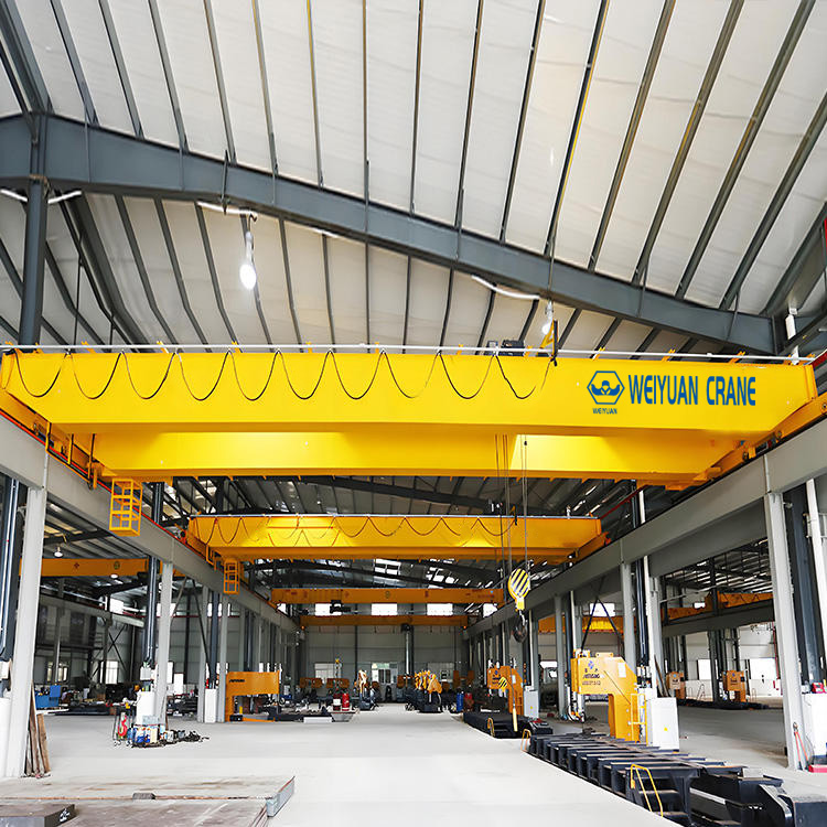
A machine shop I reviewed had bought a proper 20-tonne double-girder crane, top running on brackets — the configuration decisions from the first two articles in this series made correctly. The crane was right. The runway beam under it was a rolled wide-flange section a fabricator had picked off a standard table to “match the span.” Within two years the bracket welds had cracked, the beam sagged visibly at mid-span under load, and the crane skewed hard enough to grind its wheel flanges.
Nothing about the crane failed. The runway beam did — and it failed in three separate ways at once: too flexible for the span, a bracket connection detailed with no thought for fatigue, and no lateral bracing to resist the sideways thrust a moving crane generates. Each was a design decision nobody made deliberately. The beam was “sized” by picking a section deep enough to hold the load, and that is exactly how runway beams fail.
The runway beam is the most underestimated component in an overhead crane installation. It carries the crane’s entire weight plus the load, moving, cyclically, for the crane’s full 20-to-30-year life. Get its depth, its connection, and its bracing right and it disappears into the background. Get any one wrong and it takes the crane down with it.
This is the third and final article in our overhead crane series, following Top Running vs Under Running and Single vs Double Girder. Here we cover the runway beam itself.
What you’ll take away:
- How span-to-depth ratio and deflection limits (L/600, L/700, L/1000) actually size the beam
- When a rolled section works and when a welded plate girder becomes necessary
- Why the bracket connection is a fatigue detail, not just a strength detail
- What lateral bracing and alignment the beam needs to keep the crane running true
- CMAA Spec No. 70 and AISC Design Guide 7 references you can hand to your engineer
- 2026 cost benchmarks so the runway steel doesn’t ambush your budget
Part 1: Span, Depth & Deflection — What Really Sizes the Beam
The single most common runway beam error is sizing for strength when the beam is actually governed by deflection. Almost any adequate steel section can hold the wheel loads without yielding. The beam is sized so it holds those loads without sagging past a strict limit — because a runway beam that deflects too much lets the crane run downhill toward mid-span, skews the wheels, and stresses every connection.
Deflection Limits Are Stricter Than You Expect
Runway beam deflection is expressed as a fraction of the span, L. The larger the denominator, the stiffer the beam has to be.
| Deflection limit | Where it applies | Duty context |
|---|---|---|
| L/600 | Vertical deflection, lighter-duty runways (CMAA Class A–C) | Intermittent, single-shift service |
| L/700 to L/800 | Vertical deflection, moderate to heavy duty | Frequent production lifting |
| L/1000 | Vertical deflection, heavy/continuous duty (Class D–F); lateral deflection often ~L/400 | High-cycle, multi-shift service |
A 24-metre runway at L/1000 may deflect no more than 24 mm under the maximum wheel loads. That’s a demanding target, and it’s what forces long-span runway beams to be deep and heavy — not the raw strength, the stiffness.
The Span-to-Depth Ratio Rule of Thumb
Before any detailed calculation, a span-to-depth ratio gives you a sanity check on beam depth:
- Light duty: beam depth roughly L/18 to L/20
- Moderate to heavy duty: beam depth roughly L/12 to L/16
So a 15-metre heavy-duty runway wants a beam on the order of 1.0 to 1.25 metres deep. If a fabricator proposes a section far shallower than this, it’s a warning sign the beam was chosen on strength alone.
Worked Example — 15-Metre Runway, 10-Tonne Crane
   RUNWAY BEAM DEFLECTION

   Column                          Column
     │        wheel loads P          │
     │         ↓      ↓              │
   ══╪═════════════════════════════╪══  ← beam (span L = 15 m)
     │          ╲             ╱     │
     │             ╲_______╱        │   ← deflection Δ
     │          (Δ must stay within L/800)
- Span L = 15,000 mm
- Duty: CMAA Class C, moderate — target L/800
- Allowable deflection = 15,000 ÷ 800 = 18.75 mm
- Span-to-depth check at L/14 → beam depth ≈ 1,070 mm
The engineer sizes the section so calculated mid-span deflection under the worst wheel-load position stays under 18.75 mm. On a 15-metre span, that typically lands on a deep rolled section or a light plate girder — which is exactly the fork we cover next.
Section summary: the runway beam is sized by deflection, not strength. Fix the duty class, pick the deflection limit, and let that — plus the span-to-depth ratio — drive the depth. A shallow beam that “holds the load” is the machine shop’s mistake waiting to happen.
Part 2: Rolled Sections vs Welded Plate Girders
Once you know the required depth, the next decision is how to build that depth: a standard rolled section off the mill table, or a welded plate girder fabricated from plate. The span and wheel loads decide.
When a Rolled Section Works
A hot-rolled wide-flange section (or a rolled beam with a channel cap for lateral stiffness) is the economical, fast choice for shorter, lighter runways. Rolled sections are cheaper per tonne, need no fabrication beyond drilling and end preparation, and come with predictable, mill-certified properties.
Where it fits: spans up to roughly 12 to 15 metres at light-to-moderate capacity, where the deepest standard rolled section available still satisfies the deflection limit.
The common upgrade at the top of the rolled range is a capped section — a rolled beam with a channel welded to the top flange. The cap adds the lateral stiffness a runway beam needs to resist the crane’s side thrust (Part 4), and it’s a proven, economical detail before you jump to a full plate girder.
When You Need a Welded Plate Girder
Past the deepest available rolled section — driven by long span, high wheel loads, or a strict L/1000 limit — you fabricate a welded plate girder: a custom I-section built from a web plate and two flange plates welded together.
Where it fits: spans beyond ~15 metres, heavy capacities, and Class D–F duty, where you need a section deeper or stronger than any rolled beam.
   ROLLED SECTION          CAPPED SECTION         WELDED PLATE GIRDER
                            ┌──[channel cap]─┐
    ─────┬─────             ═════╤═════            ═══════╤═══════ ← flange plate
         │                       │                        │
         │  (fixed by            │  (rolled beam          │        ← web plate
         │   mill table)         │   + welded cap)         │          (custom depth)
    ─────┴─────             ─────┴─────            ═══════╧═══════ ← flange plate
The plate girder’s advantage is total control: the engineer sets web depth, flange width, and plate thickness independently to hit the exact stiffness and strength needed. The cost is fabrication — welding, and critically, the fatigue-sensitive welds that must be detailed and inspected properly.
| Factor | Rolled section | Welded plate girder |
|---|---|---|
| Span suitability | Up to ~12–15 m | 15 m and beyond |
| Cost per tonne | Lower | Higher (fabrication) |
| Depth control | Limited to mill sizes | Fully custom |
| Lead time | Short | Longer |
| Fatigue detailing | Simpler | Critical — web/flange welds |
Section summary: default to the rolled or capped section and let span, wheel load, and the deflection limit force you up to a plate girder. Don’t fabricate a plate girder where a capped rolled beam does the job — and don’t stretch a rolled beam past the depth the deflection limit demands.
Part 3: The Bracket Connection — A Fatigue Detail, Not a Strength Detail
Here is where the machine shop’s beam cracked, and where most runway failures actually originate. The bracket — the steel that projects from the column to carry the runway beam — is not a static connection. A crane runway sees the load applied and removed on every single pass, tens of thousands of cycles a year. That makes the bracket connection a fatigue problem, and fatigue is governed by the detail, not just the stress.
Why Fatigue, Not Strength, Governs
A connection can be perfectly strong for a single static load and still crack under repeated loading well below that strength. Fatigue cracks start at stress concentrations — weld toes, re-entrant corners, abrupt section changes — and grow a little on every load cycle until the connection fails. A bracket detailed only for the peak static force, with no thought to how the weld geometry concentrates cyclic stress, is the classic runway failure.
Fatigue Classification Drives the Detail
AISC and CMAA classify connection details into fatigue categories (A through E, roughly, from best to worst) based on the stress concentration the geometry creates. A smooth, ground, full-penetration weld sits in a high category and tolerates many cycles; an abrupt fillet weld across a stressed member sits low and cracks early.
The design steps that actually matter:
- Establish the load cycle count from the duty class — a Class F runway sees vastly more cycles than a Class B one, and needs a higher fatigue category to survive them.
- Detail the weld for its fatigue category — full-penetration welds where cyclic stress is high, ground transitions to remove stress raisers, and no abrupt changes in section at the connection.
- Avoid stress concentrations — no sharp re-entrant corners on the bracket, no intermittent welds in the fatigue load path, and generous transition radii.
The Lateral Force the Bracket Also Carries
The bracket doesn’t only carry the vertical wheel load down. It resists the lateral thrust the crane generates when the trolley accelerates and brakes (commonly taken as a percentage of the lifted load, per CMAA), plus the longitudinal thrust when the bridge starts and stops. The bracket-to-column connection has to carry all three — vertical, lateral, longitudinal — repeatedly, without the connection loosening or the welds cracking.
Section summary: design the bracket for fatigue first, strength second. Set the cycle count from the duty class, pick the weld details for the right fatigue category, and eliminate the stress concentrations that seed cracks. A bracket that’s strong but fatigue-blind is a two-year connection on a thirty-year crane.
Part 4: Lateral Bracing & Runway Alignment
A runway beam sized for vertical deflection and detailed for fatigue can still let the crane skew if it isn’t braced against sideways forces and held in alignment. This is the third failure the machine shop suffered — and it’s the one that turns a good beam into ground-up wheel flanges.
Why the Beam Needs Lateral Bracing
A moving crane pushes its runway sideways. When the trolley accelerates or brakes across the bridge, and when the bridge itself starts and stops, lateral forces drive into the top of the runway beam. A tall, deep beam that’s stiff vertically can be surprisingly weak sideways — its top flange wants to buckle or sway.
Two provisions handle this:
- The top-flange cap or a horizontal truss stiffens the beam against lateral bending, which is exactly why capped sections (Part 2) are the standard runway detail.
- Tie-back bracing to the columns or roof structure restrains the beam’s top flange laterally at intervals along the span, preventing lateral-torsional buckling under the crane’s side thrust.
Alignment Is a Design Requirement, Not an Install Afterthought
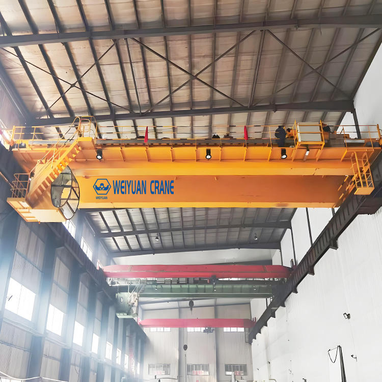
Crane wheels are rigid steel on a rigid rail, with almost no tolerance for a runway that’s out of line. If the two runway beams aren’t parallel, level, and straight within tolerance, the crane skews — and skewing grinds wheel flanges and rail sides, overloads travel motors, and feeds fatigue back into the brackets.
The alignment tolerances your installer must hold, drawn from CMAA Spec No. 70:
| Tolerance | Controls | Typical limit |
|---|---|---|
| Span (rail-to-rail) | Distance between the two runway rails | ±3 mm under 15 m span; ±5 mm larger |
| Elevation | Height difference between opposing rails | ~10 mm max, with a local rate limit |
| Straightness | Lateral wander of each rail | ±3 mm over ~10 m |
| Rail joint offset | Step where rail sections meet | ≤ 0.8 mm |
Make a documented alignment survey a condition of acceptance, and tie final payment to it. It’s the cheapest insurance on a high-value asset.
Section summary: the beam must be braced laterally and held in alignment, or the crane skews no matter how well the beam carries vertical load. Cap the top flange, tie the beam back to the structure, and hold the four alignment tolerances with a documented survey.
Part 5: CMAA Spec No. 70 & AISC Design Guide 7
Runway beam design isn’t guesswork — two documents govern it, and knowing what each covers lets you hold your engineer and fabricator to a real standard rather than a fabricator’s rule of thumb.
CMAA Specification No. 70
CMAA Spec No. 70 is the standard for top running bridge cranes (the configuration from article 1 of this series). For runway design, it supplies the crane side of the equation:
- Wheel loads — the maximum and minimum vertical wheel loads the crane delivers to the runway.
- Impact factors — the dynamic allowance added to static wheel loads (commonly 15–25%) to account for lifting and motion.
- Lateral and longitudinal thrust — the side and end forces the crane generates, as fractions of the load and crane weight.
- Duty classification — CMAA Classes A–F, which set the fatigue cycle count.
AISC Design Guide 7
AISC Design Guide 7, Industrial Buildings — Roofs to Anchor Rods, covers the structure side — how to design the runway beam, its bracket, and its connections to carry the CMAA loads:
- Runway beam design — deflection limits, section selection, and lateral-torsional buckling checks.
- Fatigue detailing — the connection categories and weld details that survive the cycle count.
- Bracket and tie-back design — carrying vertical, lateral, and longitudinal forces into the column.
How they work together: CMAA 70 tells you what forces the crane applies; AISC Design Guide 7 tells you how to build a runway that carries them for its full life. Any competent runway design references both. If a fabricator’s proposal cites neither, that’s your signal the beam was sized by eye — the machine shop’s exact starting point.
Section summary: CMAA 70 defines the loads, AISC Design Guide 7 defines the structure. Insist your runway design references both, and you’ve closed the gap that lets a fabricator “size a beam” without engineering it.
Part 6: Pulling It Together — A Runway Design Checklist
Before you approve a runway beam design or compare fabricator quotes, run the design against this sequence. It follows the exact order the engineering demands.
- Confirm the crane data (CMAA 70). Maximum wheel loads, wheel spacing, impact factor, lateral and longitudinal thrust, and duty class — all from the crane supplier.
- Set the deflection limit from the duty class. L/600 light, L/700–L/800 moderate, L/1000 heavy. This governs the beam, not strength.
- Check the span-to-depth ratio. Beam depth in the L/12–L/16 range for moderate-to-heavy duty; flag anything much shallower.
- Choose the section. Rolled or capped section up to ~12–15 m; welded plate girder beyond, or where L/1000 forces extra depth.
- Detail the bracket for fatigue. Establish the cycle count, pick weld details for the right fatigue category, and eliminate stress concentrations.
- Design lateral bracing and tie-backs. Cap the top flange and restrain it against the crane’s side thrust to prevent lateral-torsional buckling.
- Specify alignment tolerances (CMAA 70). Span, elevation, straightness, and joint offset — with a documented survey as a condition of acceptance.
- Reference the standards. Confirm the design cites CMAA 70 and AISC Design Guide 7.
Section summary: eight steps, in order, take a runway from crane data to an accepted installation. Skip any one — as the machine shop skipped steps 2, 5, and 6 — and you’ve built a failure into a thirty-year asset.
Part 7: 2026 Cost Reference for Runway Beam & Bracket Steel
Use these as planning benchmarks for the runway structure — the part of a crane project most often under-quoted or excluded from the crane price. Actual costs vary with span, capacity, duty class, region, and site access. Figures are per crane-served bay unless noted.
| Runway element | Scope | 2026 planning range (USD) |
|---|---|---|
| Rolled runway beam (supply + install) | Standard section, per linear metre per rail | $300 – $700 / m |
| Capped runway beam (beam + channel cap) | Rolled beam with welded top-flange cap, per metre | $450 – $950 / m |
| Welded plate girder runway (fabricated) | Custom plate girder, per metre per rail | $700 – $1,800 / m |
| Column brackets (fatigue-detailed) | Fabricated bracket + connection, each | $800 – $3,500 |
| Lateral tie-back bracing | Top-flange restraint to structure, per bay | $1,500 – $6,000 |
| Crane rail + fixing | Rail, clips, sole plate, per metre | $250 – $800 / m |
| Commissioning alignment survey | Professional survey to CMAA 70 tolerance | $2,500 – $9,000 |
| Runway re-alignment (early correction) | Shim/adjust drifted runway | $4,000 – $20,000 |
Two budget realities worth flagging:
- The runway can rival the crane. On a long-span or heavy-duty installation, the plate girder runway, brackets, and bracing are a genuine structural cost that can approach the price of the crane itself. A crane quote that excludes the runway isn’t cheaper — it’s incomplete.
- Fatigue detailing is cheap insurance. A properly detailed, full-penetration bracket connection costs modestly more than a quick fillet-welded one — and a fraction of the cracked-bracket repair, wheel-flange regrind, and downtime the machine shop paid for skipping it.
Procurement tip: normalize every runway quote to the same span, wheel loads, duty class, deflection limit, and fatigue detailing standard. A cheaper number often reflects a shallower beam, an under-detailed bracket, or omitted bracing — not a genuine saving. Require the design to cite CMAA 70 and AISC Design Guide 7, and make the alignment survey a condition of acceptance.
Frequently Asked Questions
Q: What deflection limit should I use for my crane runway beam?
A: Match it to the duty class. Lighter-duty runways (CMAA Class A–C) commonly use L/600 for vertical deflection; moderate-to-heavy runways use L/700 to L/800; and heavy or continuous duty (Class D–F) uses L/1000, with lateral deflection often held around L/400. The stricter the limit, the deeper and heavier the beam. Crucially, the runway beam is governed by deflection, not strength — a section strong enough to hold the wheel loads can still be far too flexible, letting the crane run downhill toward mid-span and skew its wheels. Set the deflection limit first, then size the beam to meet it.
Q: When do I need a welded plate girder instead of a rolled runway beam?
A: When the deepest available rolled section can’t satisfy your deflection limit — typically past about 12 to 15 metres of span, at high wheel loads, or under a strict L/1000 heavy-duty requirement. Below that, a rolled section (often with a channel cap welded to the top flange for lateral stiffness) is cheaper and faster. A welded plate girder lets the engineer set web depth, flange width, and plate thickness independently to hit exact stiffness, but it costs more to fabricate and introduces fatigue-sensitive welds that must be detailed and inspected properly. Default to the rolled or capped section and let span and deflection force you up to a plate girder.
Q: Why is the bracket connection treated as a fatigue problem?
A: Because a crane runway loads and unloads the bracket on every single pass — tens of thousands of cycles a year. A connection can be perfectly strong for one static load and still crack under repeated loading well below that strength, because fatigue cracks start at stress concentrations (weld toes, sharp corners) and grow a little on every cycle. AISC and CMAA classify weld details into fatigue categories, and the detail must be chosen for the cycle count the duty class implies. A bracket detailed only for peak static force, with abrupt fillet welds and no thought to stress concentration, is the most common origin of runway failure.
Q: What alignment tolerances must a crane runway hold?
A: Per CMAA Spec No. 70: span (rail-to-rail distance) within about ±3 mm under a 15-metre span and ±5 mm on larger spans; elevation difference between opposing rails within roughly 10 mm total with a local rate-of-change limit; straightness within about ±3 mm over a 10-metre length; and rail joint offset within roughly 0.8 mm. Crane wheels are rigid steel on rigid rail with almost no tolerance for misalignment, so a runway out of line makes the crane skew — grinding wheel flanges and rail sides, overloading travel motors, and feeding fatigue into the brackets. Make a documented alignment survey a condition of acceptance.
Q: Which standards govern crane runway beam design?
A: Two work together. CMAA Specification No. 70 defines the crane side — the wheel loads, impact factors, lateral and longitudinal thrust, and the Class A–F duty rating that sets the fatigue cycle count. AISC Design Guide 7 (Industrial Buildings — Roofs to Anchor Rods) defines the structure side — runway beam deflection and buckling design, fatigue detailing of connections, and bracket and tie-back design to carry the loads into the columns. CMAA 70 tells you what forces the crane applies; Design Guide 7 tells you how to build a runway that carries them for its full life. A competent runway design references both — if a proposal cites neither, the beam was likely sized by eye.