


Overhead Crane Span & Hook Height Selection Guide
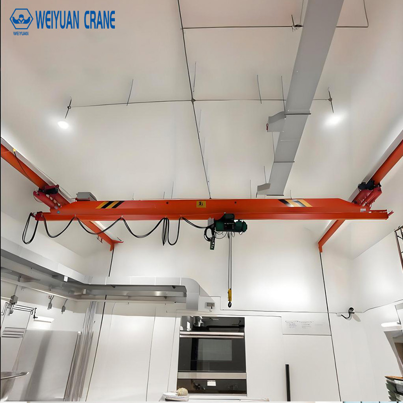
Introduction
The span and hook height of an overhead crane are the two dimensions that determine whether the crane can actually serve the facility it is installed in — whether the hook can reach every point in the working area, and whether it can be raised high enough to perform the required lifts. Yet these two dimensions are routinely specified incorrectly, producing cranes that either cannot reach important areas of the work zone or cannot lift to the height required for the application.
The consequences range from operational inconvenience to complete application failure. A crane with a span that is too narrow leaves dead zones at the edges of the work area where the hook cannot reach — forcing operators to manually move loads into the crane’s coverage zone before lifting, defeating the purpose of the crane. A crane with insufficient hook height forces operators to perform lifts in stages — lowering the load to an intermediate position, repositioning, and lifting again — adding time, handling steps, and safety risk to every affected lift cycle.
Getting span and hook height right requires systematic calculation from the specific dimensional requirements of the application — not from rough estimates, round numbers, or matching a competitor’s existing crane. This guide provides the complete methodology: how to determine the required span from the facility layout, how to calculate the required hook height from the lift path analysis, the building structural requirements that establish the available envelope, and the specification mistakes that most commonly result in undersized or oversized crane systems.
Part 1: Understanding the Crane Coverage Geometry
Before calculating specific dimensions, it is important to understand what span and hook height mean operationally and how they interact to define the crane’s three-dimensional working envelope.
What Span Determines
The crane’s span is the center-to-center distance between the two runway rails. This dimension determines the maximum lateral width of the working area that the crane can serve — the trolley can travel from directly below one rail to directly below the other rail, giving the crane coverage of the full width between the runway rails.
The working area that the crane actually covers is narrower than the rail-to-rail span by the minimum approach distance at each side — the minimum distance from the runway rail centerline to the nearest point the hook can travel. This minimum approach is typically 200 to 400mm for underhung single-girder cranes and 300 to 600mm for top-running cranes, depending on the end truck design and trolley wheel spacing.
Effective working width = Span − (2 × minimum approach distance)
For a 20-meter span crane with 400mm minimum approach on each side: Effective working width = 20.0 − 0.8 = 19.2 meters.
The working area that the crane cannot cover — the zone outside the runway rails where the hook cannot reach — is the operational dead zone. Any process, equipment, or material storage positioned outside this zone cannot be served by the crane without moving the load into the coverage area first.
What Hook Height Determines
The hook height is the vertical distance from the floor to the hook centerline at its highest position. This is the maximum elevation that the bottom of the suspended load can reach — defined by the hook height minus the distance from the hook to the top of the load.
Hook height determines whether the crane can:
- Lift loads over obstacles in the travel path (machine guards, equipment, mezzanine edges, adjacent stacked material)
- Reach the required deposit position height (mezzanine level, elevated fixture, rack system)
- Provide adequate vertical clearance between the load bottom and the floor when the load is traveling at maximum height
A crane that cannot raise its hook high enough to clear obstacles in the travel path must travel slowly with the load at a low height, relying on operators to manage the risk of contact with floor-level obstructions — an operationally constrained and unsafe workflow.
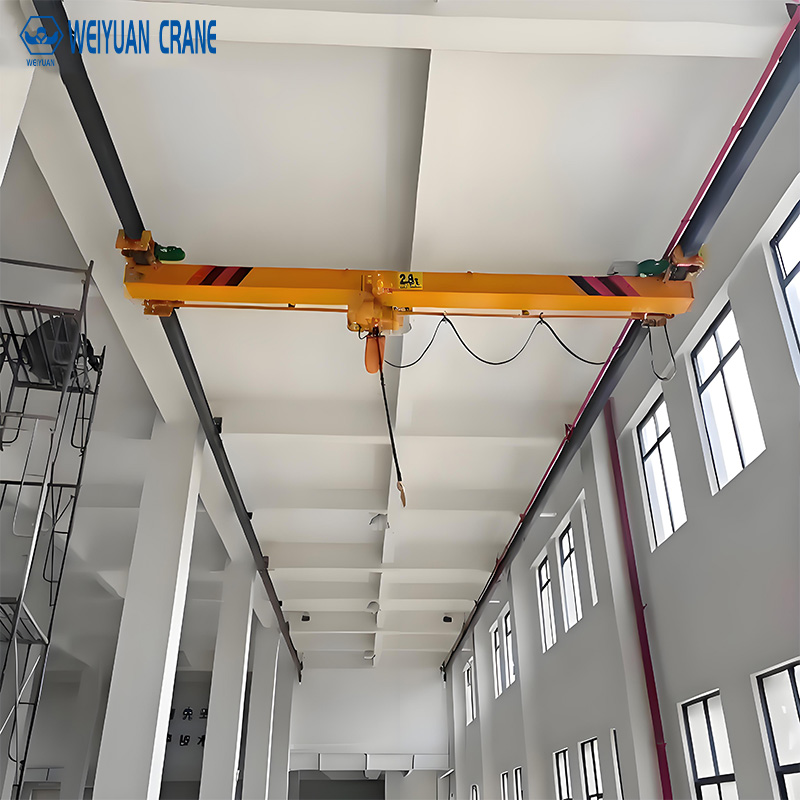
Part 2: Span Selection Methodology
Step 1: Map the Work Area Coverage Requirement
Define the rectangular area of the floor that the crane must be able to serve. This is not necessarily the full building floor area — it is the area within which loads must be picked up, transported, and deposited.
Mark on a floor plan:
- All pickup positions (machine discharge points, receiving areas, staging racks)
- All deposit positions (processing equipment, storage positions, outbound shipping areas)
- The rectangle that encompasses all pickup and deposit positions
The crane’s runway must be positioned so that the effective working width covers this rectangle. If the rectangle is 18 meters wide, the runway must be at least 18 + 2 × minimum approach = 18.8 meters wide at minimum. Specify 19 meters for a comfortable margin.
Step 2: Verify Building Column Spacing
The runway beams are supported by building columns, and the runway rail centerlines must be positioned to allow the runway beams to span between the building column rows on each side. The runway rail centerline is typically positioned 200 to 400mm inboard of the building column centerline — close enough to be supported efficiently, but far enough inboard that the crane’s end trucks clear the columns during travel.
For an existing building with column rows 18 meters apart: the runway rails at 17.2 meters span (200mm inboard on each side) provide an effective working width of 17.2 − 0.8 = 16.4 meters.
If this is narrower than the required working width, the options are: reposition one runway rail outboard (requiring a new column or cantilevered runway beam bracket), use a wider building, or accept the reduced coverage and adjust the facility layout accordingly.
Step 3: Check Building Structure Adequacy for the Crane Loads
The building columns and runway beams must carry the weight of the crane bridge, the trolley and hoist, and the maximum lifted load — plus dynamic impact loads. This structural check must be performed by a licensed structural engineer before specifying the runway span and beam size.
For new facilities, the building can be designed around the crane requirements. For existing facilities, the structural check frequently reveals that the existing columns cannot carry the crane loads without reinforcement — a cost that must be factored into the crane system budget.
Part 3: Hook Height Calculation Methodology
Hook height calculation is a sequential dimensional analysis that identifies every vertical element in the crane’s lift path and sums them to determine the required hook height.
The Complete Hook Height Formula
Required hook height = maximum lifted load height + maximum lifted load elevation at deposit position + rigging height above load top + safety clearance
Where:
- Maximum lifted load height = vertical dimension of the tallest load at the moment of maximum elevation in its travel path
- Maximum lifted load elevation at deposit position = height of the deposit point above the floor (top of rack, mezzanine floor elevation, machine table height, etc.)
- Rigging height above load top = distance from the top of the load to the hook centerline, accounting for the sling angle and any spreader beam or lifting fixture above the load
- Safety clearance = minimum vertical clearance between the bottom of the crane bridge and the top of the load at maximum elevation (typically 200 to 500mm minimum)
Worked Example
Application: Machine shop crane lifting engine blocks from a floor-level machining table and placing them on a mezzanine-level inspection fixture.
Tallest engine block height: 700mm
Mezzanine inspection fixture elevation (top of fixture above floor): 3,200mm
Rigging height (sling from engine lifting lugs to hook): 600mm
Safety clearance (bridge bottom to top of engine block at mezzanine elevation): 300mm
Required hook height = 700 + 3,200 + 600 + 300 = 4,800mm (4.8 meters)
This means the hook must be able to reach 4.8 meters above the floor to perform the mezzanine deposit lift. Any crane system that provides less than 4.8 meters of hook height cannot serve this application.
The Headroom Budget
The hook height calculation tells you how much hook height the crane needs. The building clear height tells you how much space is available. The difference — the headroom budget — determines what crane configuration is feasible:
Available hook height = Building clear height − runway beam depth − bridge beam depth − hoist body height (hook approach)
For a building with 7.0 meters clear height, 400mm runway beam, 350mm bridge beam, and 550mm hook approach (standard single girder chain hoist): Available hook height = 7,000 − 400 − 350 − 550 = 5,700mm.
Since required hook height is 4,800mm and available is 5,700mm, the application works with a standard configuration with 900mm of margin.
If the required hook height were 5,500mm in the same building, the margin would be only 200mm — acceptable but tight, and worth verifying with detailed crane dimensional data before ordering.
If the required hook height exceeded the available hook height by any amount: the application cannot be served by a standard crane configuration. Options include: low headroom European hoist (reduces hook approach by 200 to 400mm), double girder top-running configuration (provides maximum hook height), structural modification to raise the runway elevation, or accepting that the mezzanine deposit elevation must be reduced.
Part 4: Runway Layout Optimization
Beyond span and hook height, the runway layout — the positioning and length of the two parallel runway rails — determines the full working envelope of the crane system.
Runway Length
The runway length must be adequate to cover the full longitudinal extent of the work area, plus overrun at each end to allow the crane end trucks to clear the last work station position while still providing adequate stopping distance.
Required runway length = Work area length + 2 × end overrun
End overrun is typically 500 to 1,500mm depending on bridge travel speed and the brake deceleration rate. For a work area 30 meters long with 800mm overrun at each end: Required runway length = 30 + 1.6 = 31.6 meters. Specify 32 meters.
Column Spacing and Runway Beam Span
Runway beams span between building columns. The column spacing determines the runway beam span, which directly affects the runway beam size and cost. Shorter column spacing allows lighter runway beams; longer column spacing requires deeper, heavier beams.
For a standard production overhead crane (10 to 20 tons, CMAA Class C), a runway beam span of 6 to 8 meters is typically the economic optimum — deep enough to maintain adequate stiffness for the crane loads without excessive beam weight. For light cranes (1 to 5 tons), 8 to 12-meter runway beam spans are often practical. For heavy cranes (50 tons and above), column spacing of 5 to 6 meters is common to limit runway beam size.
Two-Crane Runway Systems
When two cranes share the same runway, the runway length must accommodate both cranes plus minimum spacing between them. The minimum spacing is determined by the crane’s end truck length plus clearance for the anti-collision system to function — typically 1.5 to 3 meters minimum separation between adjacent crane bridges.
For two cranes each 3 meters long with 2 meters minimum separation: minimum runway travel distance between end stops = 3 + 2 + 3 = 8 meters. The runway must be long enough that both cranes can travel their full required working length without this constraint forcing one crane to block the other.
Part 5: Common Sizing Mistakes and How to Avoid Them
Specifying span from building column spacing without checking minimum approach: The effective working width after subtracting minimum approach from both sides may be narrower than assumed. Always subtract minimum approach to determine actual coverage.
Specifying hook height based on the typical lift rather than the critical lift: The crane must be sized for its most demanding lift — the one with the greatest height requirement. If 95% of lifts require only 3.0 meters of hook height but one lift per shift requires 4.8 meters, the crane must be specified for 4.8 meters.
Forgetting to include rigging height in the hook height calculation: Slings, shackles, spreader beams, and lifting fixtures between the hook and the load top all consume vertical space that reduces the effective hook height available for the load itself. For a 1.0-meter spreader beam + 0.5-meter slings, 1.5 meters of hook height is consumed before the load is even reached.
Not accounting for future load growth: A crane specified for today’s maximum lift that will be used for 20 years should anticipate reasonable growth in maximum load weight and deposit elevation. Specifying 10 to 15% above the current maximum requirement provides growth headroom without significant additional cost.
Matching a competitor’s existing crane dimensions without independent analysis: The competitor’s crane may have been incorrectly specified, may serve a different workflow than yours, or may have been accepted as a compromise when the correct size was not available. Always derive dimensions from your own application analysis.
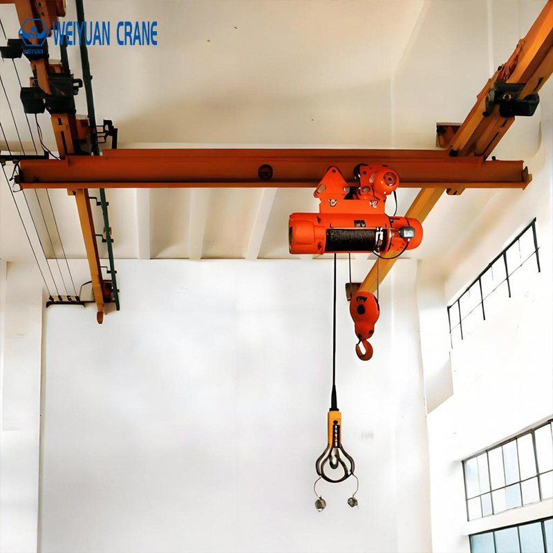
Frequently Asked Questions
Q: What is the minimum building clear height required for a 5-ton overhead crane?
A: This depends entirely on the required hook height for the application. There is no universal minimum — the calculation must be done for each specific application as described in this guide. A 5-ton crane in a facility requiring only 3.0 meters of hook height may fit in a 5.5-meter clear height building. The same 5-ton crane in a facility requiring 6.0 meters of hook height needs at least an 8-meter clear height building (and possibly more, depending on the hoist configuration).
Q: Can the runway span be extended after the crane is installed?
A: Extending the runway span requires adding new runway beams and columns at a wider spacing, installing longer end trucks on the crane bridge, and replacing the bridge girder with a longer one. This is essentially rebuilding the crane system. It is not a simple extension. The cost of span extension after installation is typically comparable to the cost of the original installation — strongly justifying a careful span analysis before the original installation.
Q: What is a “double reeving” configuration and how does it affect hook height?
A: Double reeving uses two rope runs between the drum and the hook block rather than one, halving the load on each rope segment. This allows a smaller drum and motor for the same capacity — but the hook block must be deeper to accommodate the additional sheave, which consumes some hook height. For headroom-constrained applications, single reeving with a larger motor may provide better hook height at the cost of a higher-rated motor.