


Wall-Mounted Jib Crane Guide

Introduction
A wall-mounted jib crane looks like the simplest lifting device in the building. A horizontal arm bolted to a wall, a hoist hanging from it, a load swinging through an arc. Pick an arm long enough, bolt it up, and lift. That is how most people picture it, and that picture is exactly what gets walls cracked and brackets torn loose.
A wall-mounted jib crane does not press straight down on the wall the way a shelf does. It hangs a load out at the end of a cantilever, and that lever arm multiplies the load into a powerful tipping moment at the wall connection. A modest 500 kg load on a 4 m arm does not put 500 kg on the wall. It puts a turning force on the anchor bolts equal to thousands of kilograms of pull at the top row and an equal push at the bottom row — and that force reverses direction every time the crane swings to the other side. The wall and its anchors are not carrying weight. They are fighting a moment that flips back and forth thousands of times a year.
That is where standard brackets fail. A shelf bracket, a pipe support, or a generic wall fixing is designed for a static downward load. It has no provision for the overturning moment a jib crane generates, no fatigue rating for the reversing load cycles, and no understanding of how the building structure behind the wall actually carries the reaction into the frame. Bolt a jib crane to a bracket rated for static weight and the anchors loosen, the wall face cracks, and within a year or two the arm sags or the connection pulls out of the masonry entirely.
A wall-mounted jib crane is a structural load-transfer device first and a lifting device second. It must turn the cantilevered moment into a clean couple at the wall, deliver that couple into a structural element that can actually accept it, control deflection so the load does not run downhill toward the arm tip, and detail every anchor as a fatigue-loaded connection rather than a static one.
This guide covers the complete framework for specifying a wall-mounted jib crane: the application categories and where each type fits, the corrosion and load specifications, the rotation arc and structural load transfer that define the design, CMAA duty classification, foundation and wall anchor design, the common errors that cause early failure, and a 2026 price reference. By the end you will understand why the wall connection — not the arm — is the part that deserves the most attention.
Part 1: Application Categories
The way a wall-mounted jib crane is used sets its capacity, its outreach, its rotation arc, and how its load must be transferred into the building. Three categories cover the vast majority of installations.
Category 1: Workstation Jib Cranes
Workstation wall-mounted jibs serve a single operator position — a welding bay, a machine-loading station, an assembly cell, or a packing line. The crane lifts tools, fixtures, and components within a small radius, repeatedly, through a working shift.
- Typical capacity: 125 kg to 1 tonne.
- Typical outreach: 2 to 4 m.
- Rotation: commonly 180°, since the wall blocks the back half of the circle.
- Duty: moderate to heavy cycling, often CMAA Class C–D, because workstation lifts repeat constantly.
The defining feature is high cycle count at modest load. The connection sees its reversing moment thousands of times per shift, so fatigue detailing matters more than raw strength.
Category 2: Secondary Coverage Under a Bridge Crane
A wall-mounted jib is often installed beneath an overhead bridge or gantry crane to handle small, frequent lifts the big crane should not be tied up with. The bridge crane handles the heavy, infrequent moves; the wall jib handles the light, constant ones in a corner of its sweep.
- Typical capacity: 250 kg to 2 tonnes.
- Typical outreach: 3 to 5 m.
- Rotation: 180°, tucked against a column line or wall.
- Duty: moderate, CMAA Class C, supporting the main crane’s workflow.
This arrangement frees the bridge crane for its real job and shortens cycle times for routine handling, but it places the jib’s reaction into the same columns that carry the runway — a coordination point covered in Part 5.
Category 3: Outdoor and Process-Area Jibs
Wall-mounted jibs also serve loading docks, outdoor equipment bays, pump stations, and process areas where a load must be lifted off a truck, a skid, or a maintenance point against a building face.
- Typical capacity: 500 kg to 3 tonnes.
- Typical outreach: 3 to 6 m.
- Rotation: 180°, sometimes less where adjacent structure intrudes.
- Duty: light to moderate, but with environmental exposure that drives corrosion protection.
The defining challenge here is not cycle count but environment — salt air, washdown, temperature swing, or chemical exposure — which pushes the coating and hardware specification well above an indoor workstation jib.
Bottom line: match the crane to its real duty — workstation jibs cycle hard at low load, secondary-coverage jibs share their building’s columns, and outdoor jibs need environmental protection — and let that duty drive the connection design, not just the arm length.
Part 2: Corrosion Protection and Load Specifications
Two specifications frame every wall-mounted jib before the structural design begins: how it is protected against its environment, and how its loads are defined. Get these wrong and even a perfectly sized arm fails early.
Defining the Load Inputs
The load on a wall-mounted jib is never just the rated load. The structural design uses a combined figure:
- Rated load (SWL): the maximum working load on the hook.
- Hoist and trolley weight: dead weight running along the arm, which adds to the moment at full outreach.
- Arm self-weight: the cantilever’s own weight, acting at its center of gravity.
- Dynamic factor: an impact allowance per the duty class, amplifying the lifted load for the jerk of lifting and the acceleration of slewing and trolley travel.
The worst case is always the hoist at full outreach with the rated load and the dynamic factor applied — this produces the maximum moment at the wall connection, which governs the whole design.
Indoor Coating Specification
For a sheltered indoor workstation jib, the corrosion demand is modest — ISO 12944 category C2 to C3. A standard system suffices:
- Surface preparation to a clean, sound profile.
- Zinc-rich or epoxy primer.
- Polyurethane or alkyd topcoat.
- Total dry film thickness around 120–160 µm.
Outdoor and Aggressive Environments
An outdoor dock jib or a washdown process-area jib lives in ISO 12944 C4 to C5-M (marine) territory, and the coating must step up accordingly:
- Surface preparation: Sa 2.5 near-white blast.
- Zinc-rich epoxy primer (~80 µm) for galvanic protection.
- Epoxy intermediate barrier coat (~100 µm).
- Polyurethane or polysiloxane topcoat (~80 µm).
- Total dry film thickness ~260 µm, heavier near splash or washdown zones.
For severe marine or chemical exposure, hot-dip galvanizing of the arm and bracket before painting adds decades of base protection.
Hardware and Fastener Specification
- Indoor: zinc-plated or galvanized fasteners are adequate.
- Outdoor C4–C5: hot-dip galvanized anchor bolts and fittings, or type 316L stainless steel for the most exposed connections.
- Slewing bearing: sealed and packed with grease matched to the environment — marine-grade calcium-complex grease for outdoor and washdown service.
Bottom line: define the load as the worst-case combination of rated load, dead weights, and dynamic factor at full outreach, then match the coating and hardware to the real environment — indoor jibs take a standard system, while outdoor and washdown jibs need a full marine-grade build.
Part 3: Rotation Arc and Structural Load Transfer
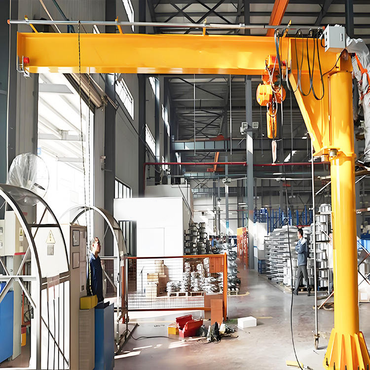
This is the heart of wall-mounted jib design. The arm reaches out, the load hangs at the end, and the wall connection must absorb a moment that reverses as the crane swings. Understanding how that moment becomes a force at the anchors is what separates a connection that lasts decades from one that tears out in a year.
The Cantilever Moment
A wall-mounted jib is a cantilever beam fixed at the wall. The load at the arm tip creates a bending moment at the fixed end equal to the load multiplied by its distance from the wall:
Moment at wall = (Rated load + hoist weight) × outreach × dynamic factor + arm self-weight × (outreach ÷ 2)
This moment is the single most important number in the design. Notice that outreach multiplies the load directly — doubling the arm length doubles the moment for the same load. This is why outreach and capacity trade against each other, covered later in this part.
How the Moment Becomes a Force Couple
The wall connection cannot resist a moment by magic — it resists it by turning the moment into a couple: a tension force at the top of the bracket and an equal compression force at the bottom, separated by the bracket height.
Connection force = Moment at wall ÷ vertical distance between top and bottom anchor rows
This relationship reveals a critical design lever: the taller the bracket, the smaller the anchor forces for the same moment. A short bracket with closely spaced anchor rows multiplies the connection force dramatically, while a tall bracket spreads the same moment into far gentler forces.
Worked Example
Consider a 500 kg wall jib with a 4 m outreach, hoist weight 80 kg, dynamic factor 1.2, and a bracket 600 mm tall:
- Load + hoist = 580 kg → 580 × 4 × 1.2 = 2,784 kg·m (plus arm self-weight, ignored here for clarity).
- Connection force = 2,784 ÷ 0.6 = 4,640 kg of tension at the top anchor row.
That single 500 kg load creates over 4.6 tonnes of pull at the top bolts. Increase the bracket height to 1.0 m and the same moment yields only 2,784 kg of anchor tension — a 40% reduction in bolt force from one geometry change.
Why the Load Reverses
When the crane swings to one side, the wall sees the moment in one direction. Swing it the other way and the moment reverses — the top anchors that were in tension now go into compression, and the bottom row goes into tension. On a 180° jib, every full sweep cycles the anchors through a complete load reversal. This is why anchor bolts must be treated as fatigue-loaded, not statically loaded, and why a connection sized only for peak strength can still crack from cyclic reversal.
Outreach vs Capacity Trade-Off
Because the moment is load times outreach, capacity and reach are locked in a trade. For a given connection and arm section:
- A longer arm at the same capacity raises the moment and the anchor forces.
- A higher capacity at the same reach does the same.
- To gain reach without overloading the wall, you must reduce capacity, deepen the arm, raise the bracket height, or strengthen the structure behind the wall.
There is no free outreach. Every additional meter of arm must be paid for somewhere in the load path.
Deflection Control
Beyond strength, the arm must control deflection so the load does not run downhill toward the tip. An arm that sags lets the trolley drift outward under load and reduces positioning accuracy. Wall jibs are typically held to a tip-deflection limit on the order of outreach divided by 150 to 250, which usually requires a deeper arm section than a strength check alone would demand — much like deflection governing a runway beam.
Bottom line: the cantilever moment at the wall is the governing number, it becomes a tension-compression couple at the anchors that grows smaller as the bracket gets taller, it reverses on every swing so the anchors are fatigue-loaded, and outreach and capacity always trade against each other.
Part 4: CMAA Compliance and Duty Classification
A wall-mounted jib is not exempt from the duty classification that governs every other crane. The class you assign sets the dynamic factor, the fatigue detailing, and the service life — and getting it wrong is the quiet cause of most early failures.
Why Duty Class Matters for a Small Crane
It is tempting to treat a small wall jib as a casual piece of equipment outside formal classification. That is exactly the mistake. A workstation jib lifting tools a few hundred times a shift accumulates more load cycles in a year than a heavy bridge crane does in a decade. The cycle count, not the load size, drives the fatigue demand on the connection — and the duty class is how that demand is captured.
CMAA Service Classes Applied to Jib Cranes
CMAA service classifications run from Class A (infrequent, light) through Class F (severe, continuous), based on load magnitude and the number of load cycles over the crane’s design life:
- Class A–B: infrequent or light-duty lifting — occasional maintenance jibs.
- Class C: moderate, regular use — typical secondary-coverage and light workstation jibs.
- Class D: heavy production use — busy workstation jibs cycling constantly through a shift.
- Class E–F: severe, continuous duty — rare for wall jibs but possible on high-throughput lines.
Most wall-mounted workstation jibs fall in Class C to D because of their high cycle count, even though their loads are modest.
The Dynamic Impact Factor
CMAA practice amplifies the lifted load with an impact factor to account for the dynamic effects of lifting, slewing acceleration, and trolley travel. Typical values rise with duty class:
- Class A–B: around 1.10
- Class C–D: 1.15 to 1.20
- Class E–F: 1.20 to 1.25
This factor feeds directly into the moment calculation in Part 3 — a higher duty class produces a higher moment for the same physical load, and therefore higher anchor forces.
Fatigue Detailing of the Connection
The duty class also sets the fatigue category of the connection details. Welded joints between the arm, the bracket, and any stiffeners must be checked against the allowable stress range for the expected number of cycles, following AISC or equivalent fatigue provisions. Because the wall connection reverses load on every swing, it is the most fatigue-critical detail on the whole crane — a connection adequate for static strength can still develop cracks at a weld toe under millions of reversals if the fatigue category is wrong for the duty.
Bottom line: classify a wall jib honestly by its real cycle count, not by its load size — most workstation jibs are Class C–D — and use that class to set the dynamic factor and the fatigue category of the all-important wall connection.
Part 5: Foundation and Wall Anchor Design
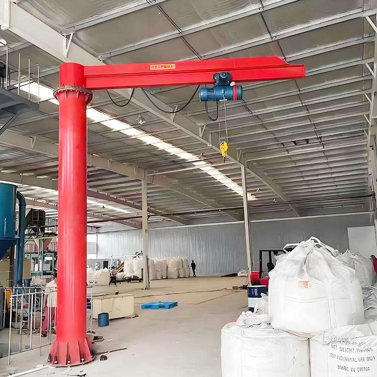
The arm and bracket are only half the load path. The other half is the structure behind the wall and the anchors that tie the crane to it — and this is where the cantilever moment finally has to go somewhere. Get this wrong and the crane is sound but the building fails around it.
What the Wall Must Actually Be
A wall-mounted jib does not bolt to “a wall” in the general sense. It must connect to a structural element capable of accepting the reaction couple — a reinforced concrete column, a steel building column, or a reinforced concrete wall designed for the load. A plain masonry or block wall, a stud partition, or a non-structural cladding panel cannot accept the tension-compression couple and will fail at the anchors. The first question in any wall-jib project is always: what is behind the wall, and can it take the moment?
Column-Mounted vs Wall-Mounted
The two common arrangements differ in how cleanly they accept the reaction:
- Steel column mounting: the bracket bolts or clamps directly to a building steel column. The column carries the couple as a horizontal force pair into the frame, and the building’s bracing handles it. This is the cleanest load path and is preferred wherever a suitable column exists. The column itself must be checked for the added bending and any local flange or web effects at the connection.
- Concrete wall or column mounting: the bracket anchors into reinforced concrete with cast-in or post-installed anchors. The concrete must have enough edge distance, embedment depth, and reinforcement to develop the tension force without a concrete breakout or pull-out failure. The anchor design must follow concrete anchorage provisions (such as ACI 318 Appendix D / Chapter 17), checking concrete breakout, pull-out, and edge failure — not just the steel strength of the bolt.
Where the existing structure cannot accept the reaction, a steel mounting column can be added — a vertical post fixed to the floor and roof structure that gives the jib a proper structural element to bolt to, independent of the wall.
Anchor Bolt Design and Fatigue
The anchors carry the tension side of the couple, and because that tension reverses on every swing, they are fatigue-loaded:
- Size for the worst-case tension from the moment couple, with the duty-class dynamic factor applied.
- Use the right anchor type: cast-in anchors or qualified heavy-duty post-installed anchors rated for cyclic tension — not lightweight expansion anchors, which lose preload under reversal.
- Detail for fatigue: maintain bolt preload to keep the joint tight under cyclic load, since a loose anchor sees far higher stress swings than a preloaded one.
- Provide edge distance and spacing so the concrete can develop the full anchor capacity without breakout.
Foundation for Floor-Mounted Posts
When a mounting post replaces an inadequate wall, it needs its own foundation — a reinforced concrete footing sized to resist the overturning moment at the base. The footing must be heavy and wide enough that the crane’s tipping moment does not lift one edge, and the base plate anchors must be designed for the same reversing tension as a wall connection.
Coordinating with the Building Structure
When a wall jib mounts to a column that also carries other loads — a runway column, for instance — the column must be checked for the combined load case: its existing building and crane loads plus the new jib reaction acting simultaneously. A column adequate for either load alone can be inadequate for both together. This coordination must happen before installation, not after a crack appears.
Bottom line: connect the jib only to a real structural element that can accept the reversing couple, prefer a clean steel-column load path, design concrete anchors for breakout and cyclic tension rather than just bolt strength, and always check the supporting structure for the combined load case.
Part 6: Common Design Errors
Most wall-jib failures trace back to a handful of repeatable mistakes. Each one is avoidable with the right check before the crane goes up.
Error 1: Treating the Load as Static Downward Weight
The most common error sizes the connection for the rated load pressing down, ignoring the cantilever moment entirely. The anchors are nowhere near strong enough for the tension the moment generates, and the connection loosens or pulls out within months.
Avoid it: calculate the moment at the wall and the resulting anchor tension as shown in Part 3, never the load alone.
Error 2: Bolting to a Non-Structural Wall
The jib is fixed to a masonry, block, or partition wall that cannot accept the reaction couple. The wall face cracks, the anchors elongate their holes, and the crane sags as the connection works loose.
Avoid it: confirm a real structural element behind the wall, or add a dedicated steel mounting post with its own foundation.
Error 3: Ignoring Load Reversal and Fatigue
The connection is checked for peak strength only, with no allowance for the load reversing on every swing. It holds under a single test lift but develops fatigue cracks at the weld toes or loses anchor preload after a year of cycling.
Avoid it: classify the duty honestly and design the connection and anchors as fatigue-loaded details for the expected cycle count.
Error 4: Maximizing Outreach Without Paying for It
A long arm is specified to reach a distant point without recognizing that outreach multiplies the moment. The connection, sized for a shorter reach, is overloaded the moment the longer arm is installed.
Avoid it: treat outreach and capacity as a trade — every extra meter raises the moment and must be matched by a deeper arm, a taller bracket, or a stronger structure.
Error 5: Short Bracket with Closely Spaced Anchors
The bracket is made short to save space or material, placing the top and bottom anchor rows close together. The small lever arm multiplies the anchor forces enormously for the same moment.
Avoid it: make the bracket as tall as practical to spread the couple, cutting anchor forces directly.
Error 6: Using Lightweight Expansion Anchors
Generic expansion anchors are used for the connection. Under reversing tension they gradually lose grip and back out, and the crane’s connection deteriorates with every swing.
Avoid it: specify cast-in or qualified heavy-duty anchors rated for cyclic tension, installed to the correct preload.
Bottom line: most wall-jib failures come from ignoring the moment, anchoring to the wrong structure, skipping fatigue, over-reaching the arm, undersizing the bracket height, or using the wrong anchors — each cheap to fix in design and expensive to fix after the wall cracks.
Part 7: 2026 Price Reference
These ranges frame budgeting only. Final pricing depends on capacity, outreach, rotation, duty class, environment, and mounting type. Contact WEIYUAN for a quote matched to your installation.
| Wall jib configuration | Indicative capacity & outreach | 2026 price range (USD) |
|---|---|---|
| Light workstation jib, indoor | 125–250 kg, 2–3 m | $900 – $2,500 |
| Standard workstation jib, indoor | 500 kg, 3–4 m | $2,200 – $5,000 |
| Medium-duty wall jib, indoor | 1 t, 4–5 m | $4,500 – $9,500 |
| Heavy wall jib, indoor | 2 t, 4–5 m | $8,000 – $18,000 |
| Outdoor / washdown jib (C4–C5 coating, galvanized hardware) | 500 kg–1 t, 4 m | $6,000 – $14,000 |
| Wall jib on added steel mounting post (with foundation) | 1–2 t, 4–5 m | $9,000 – $22,000 |
Cost comparison takeaways:
- A wall-mounted jib is far cheaper than a free-standing floor-mounted jib of the same capacity, because it borrows the building’s existing structure instead of needing a large foundation — provided that structure can actually accept the reaction.
- The biggest hidden cost is structural remediation: if the wall cannot take the moment, the cost of adding a mounting post and foundation, or reinforcing a column, can exceed the crane itself. Confirm the structure before pricing the crane.
- An outdoor marine-grade coating adds roughly 40 to 60% over a standard indoor finish, but against years of corrosion section loss on an exposed jib, it is among the cheapest insurance in the specification.
Frequently Asked Questions
Q: Can I mount a jib crane on any solid wall, or does it need a special structure?
A: It needs a real structural element behind the connection — a reinforced concrete column, a steel building column, or a reinforced concrete wall designed for the load. A wall-mounted jib does not press straight down; it applies a reversing tension-compression couple to the wall as the load swings, and a plain masonry, block, or partition wall cannot accept that couple. It will crack and the anchors will pull loose. Always confirm what is behind the wall first. Where no suitable structure exists, the standard solution is a dedicated steel mounting post fixed to the floor and roof with its own foundation, giving the jib a proper element to bolt to independent of the wall.
Q: How does outreach affect the capacity I can lift?
A: Directly and unforgivingly, because the load on the connection is the lifted weight multiplied by the outreach. A 500 kg load at 4 m creates twice the moment of the same load at 2 m, and that moment drives the anchor forces. So for a given connection and arm, gaining reach means losing capacity unless you also deepen the arm, raise the bracket height, or strengthen the structure behind the wall. There is no free outreach — every extra meter must be paid for somewhere in the load path. Decide the maximum reach and the maximum load you genuinely need, and size the whole connection for that worst-case combination at full outreach.
Q: Why does my wall jib’s connection keep loosening over time?
A: The usual cause is that the load reverses on every swing and the connection was never designed for it. On a 180° jib, swinging from one side to the other flips the anchor forces — the bolts that were in tension go into compression and back again, thousands of times a year. Lightweight expansion anchors gradually lose grip under this reversal and back out, and welds with the wrong fatigue category crack at the toe. The fix is to treat the connection as a fatigue-loaded detail: classify the duty by cycle count, use cast-in or qualified heavy-duty anchors rated for cyclic tension, install them to the correct preload, and make the bracket tall enough to keep the anchor forces low.
Q: Is a wall-mounted jib cheaper than a free-standing floor-mounted jib?
A: Usually yes, when the building structure can accept the load. A wall-mounted jib borrows the existing column or wall to carry its reaction, avoiding the large reinforced foundation a free-standing floor-mounted jib needs to resist its own overturning. That makes the wall jib both cheaper and quicker to install. The exception is when the wall cannot take the moment — then you need to add a steel mounting post and foundation or reinforce a column, and that remediation can cost more than the crane. So the honest answer is: a wall jib is cheaper if and only if you have a suitable structure to mount it to. Confirm the structure before assuming the saving.