
What Is a Bridge Crane? Types, Key Components & How EOT Cranes Work
Published by: [Your Brand] Engineering Team | Last Updated: March 2026 | Reading Time: 9 min
Introduction
A bridge crane — also called an Electric Overhead Traveling crane (EOT crane) or simply an overhead crane — is one of the most widely used material handling systems in industrial facilities worldwide. From automotive assembly plants and steel mills to pharmaceutical warehouses and shipyards, bridge cranes are the backbone of heavy lifting operations that cannot be served by forklifts, conveyors, or floor-level handling equipment.
Despite their ubiquity, the term “bridge crane” is often used loosely, and the distinctions between different bridge crane types — single girder, double girder, top-running, under-running — are frequently misunderstood during the procurement process. Choosing the wrong type for an application results in a crane that either underperforms the requirements or is significantly over-specified and over-priced.
This guide provides the definitive introduction to bridge cranes: what they are, how they work, the main types and their differences, the key components that make up every EOT crane system, the industries and applications where they deliver maximum value, and the specification variables that determine which bridge crane is right for your facility.
Part 1: What Is a Bridge Crane?
A bridge crane is a type of overhead material handling system in which a horizontal bridge beam — or pair of beams — spans the width of a working area and travels along elevated runway rails installed on or attached to the building structure. A hoist and trolley assembly mounted on the bridge provides vertical lifting and horizontal cross-travel across the bridge span.
The name “bridge crane” comes from the structural analogy: the horizontal crane bridge “spans” the working area below, just as a road bridge spans a river or gap. The bridge travels longitudinally (along the length of the building or runway) while the trolley travels transversely (across the width of the building, along the bridge). Together, the two travel axes give the hoist access to any point within the rectangular working envelope beneath the runway.
The term EOT crane (Electric Overhead Traveling crane) is the formal engineering designation used in standards documents, specifications, and engineering drawings. It emphasizes the three defining characteristics: electrically powered, overhead-mounted, and capable of traveling along the runway. In everyday industrial use, EOT crane, bridge crane, and overhead crane are used interchangeably to describe the same equipment category.
Bridge cranes are fundamentally different from gantry cranes — a closely related category — in one key respect: bridge cranes are supported by the building structure (runway beams attached to building columns or walls), while gantry cranes have their own freestanding legs that run on ground-level rails. This distinction has important implications for installation cost, flexibility, and the structural requirements placed on the building.
Part 2: How a Bridge Crane Works — The Operating Principle
A bridge crane moves loads through three independent motions that can be operated simultaneously or independently:
Long travel (bridge travel): The entire crane bridge, including the trolley and suspended load, travels along the runway rails in the longitudinal direction — along the length of the building. This motion is driven by bridge travel motors mounted on the end trucks that drive rubber-tired or flanged steel wheels along the runway rail.
Cross travel (trolley travel): The trolley — the assembly carrying the hoist mechanism — travels transversely along rails mounted on (or under) the bridge girder. This motion is driven by the trolley travel motor. Cross travel positions the hook anywhere across the full width of the crane’s span.
Hoisting (vertical lift): The hoist mechanism raises and lowers the hook and suspended load vertically. The hoisting motion is driven by the hoist motor through a gear reduction that turns the rope drum (wire rope hoists) or pocket wheel (chain hoists). The combination of these three motions allows the bridge crane to position a load at any point within the three-dimensional working envelope — any longitudinal position along the runway, any transverse position across the span, and any vertical height within the hoist’s lift range.
Power is supplied to the moving crane bridge through a conductor bar system (also called a busbar or festoon system) installed alongside the runway. The conductor bar carries electrical power to sliding collector contacts on the crane end truck, which then distribute power to the bridge motors, trolley motors, hoist, lighting, and control systems.
Operators control bridge cranes via a wired pendant control (hanging below the bridge on a retractable cord), a wireless radio remote control, or from an enclosed cab mounted on the crane bridge for high-capacity production cranes.
Part 3: The Four Main Types of Bridge Cranes
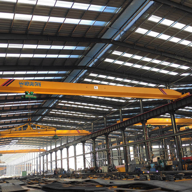
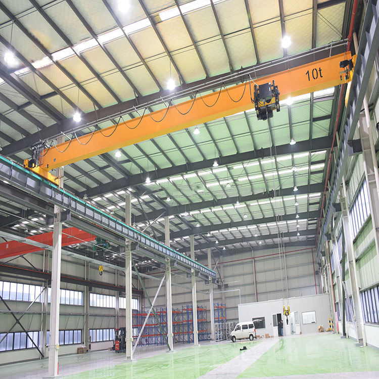
Type 1: Top-Running Single Girder Bridge Crane
The most widely installed bridge crane configuration globally. A single horizontal bridge girder spans between two end trucks. The hoist and trolley run on the bottom flange of the single bridge beam — an underhung configuration.
Key characteristics:
- Capacity range: 1/2 ton to approximately 20 tons (standard); some designs reach 32 tons
- Span range: 10 to 30 meters
- Duty class: CMAA Class A through C (standby to moderate service)
- Hook height: Limited by the hoist body height below the bridge beam — lower than equivalent double girder configurations
- Cost: The most economical bridge crane configuration for light to moderate duty applications
Best applications: Light to moderate manufacturing and assembly, warehouse material handling, maintenance workshops, small to medium fabrication facilities, and any application where the capacity and span fall within the single girder design’s performance envelope.
Limitations: Lower hook height than double girder at equivalent building clearance, greater susceptibility to lateral load-induced torsion at higher capacities, and lower maximum capacity than double girder designs.
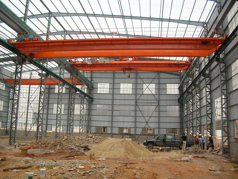
Type 2: Top-Running Double Girder Bridge Crane
Two parallel horizontal bridge girders span between the end trucks. The trolley and hoist (called a crab) runs on rails mounted on top of the two bridge beams — a top-running configuration that provides superior hook height relative to single girder designs.
Key characteristics:
- Capacity range: 5 tons to 500+ tons; practical standard range 5 to 200 tons
- Span range: 10 to 60+ meters
- Duty class: CMAA Class C through F (moderate to continuous severe service)
- Hook height: Superior to single girder — the top-running crab minimizes the distance between the lowest hook position and the bottom of the bridge structure
- Cost: Higher than single girder due to additional structural material and more complex crab assembly
Best applications: Heavy manufacturing (steel, automotive, aerospace), production lines requiring high duty cycles, foundries and forge shops, shipbuilding, and any application requiring capacity above 20 tons or maximum hook height utilization.
Type 3: Under-Running (Underhung) Single Girder Bridge Crane
Structurally similar to a top-running single girder crane but the end trucks hang from the bottom flange of the runway beam rather than running on top of it. Both the bridge and the trolley run on the bottom flanges of their respective beams.
Key characteristics:
- Capacity range: 1/4 ton to approximately 5 tons (standard)
- Span and runway: Can utilize existing building structure (roof trusses, roof beams) as the runway — eliminating the need for a dedicated runway structure
- Headroom: Provides the lowest possible hook height in a given building by using the existing building steel as the runway
- Installation cost: Often the lowest-cost bridge crane installation when suitable building steel is present
Best applications: Light-duty material handling in facilities where the building structure can serve as the runway, modular production workstations, facilities with very limited headroom where every inch of hook height is critical.
Limitations: Restricted to light capacities; the building structure must be evaluated by a structural engineer for adequacy to carry underhung crane loads before installation.
Type 4: Double Girder Top-Running Crane with Cab Control
A variant of the standard double girder crane equipped with an enclosed operator cab mounted on the bridge structure. The cab provides the crane operator with a direct line of sight to the working area below and allows precise control of heavy or sensitive lifts that pendant or radio remote operation cannot match.
Key characteristics:
- Typically used for capacities of 30 tons and above
- Standard in steel mills, foundries, heavy fabrication, and shipbuilding
- Cab equipped with heating, air conditioning, and ergonomic seating for operators who spend entire shifts in the crane
- Higher total crane cost due to cab structure, cab control systems, and operator access provisions
Part 4: Key Components of Every Bridge Crane
Understanding the major components of a bridge crane helps in evaluating specifications, identifying maintenance needs, and communicating with suppliers and service technicians.
Bridge Structure
The bridge is the main horizontal structural element that spans the working area. It consists of:
- One or two main girders (the primary load-carrying beams)
- End trucks at each end of the bridge, connecting the girders to the runway
- Walkways or catwalks on the bridge for maintenance access (required on bridges with top-mounted hoist rails)
- Electrical conductor or festoon system for power distribution from runway to trolley
The bridge girder design — box section, I-beam, truss, or built-up plate girder — is determined by the span, capacity, and duty class requirements. Long-span, heavy-duty bridges typically use box section girders for superior stiffness and torsional resistance.
End Trucks
The end trucks connect the bridge girder(s) to the runway rails and carry the bridge travel wheels. Each end truck contains:
- Drive wheels (powered, connected to the bridge travel motor and gearbox) and idler wheels
- Bridge travel motor and gearbox (on drive end trucks)
- Wheel flanges that guide the crane along the runway rail
- Buffer assemblies and end stop provisions
- Current collectors for power pickup from the runway conductor system
End truck wheel diameter and tread hardness are sized for the wheel load and the expected number of load cycles over the crane’s design life — a direct function of the duty class specification.
Trolley and Hoist
The trolley is the assembly that travels along the bridge and carries the hoist. For double girder top-running cranes, the trolley (crab) is a self-contained unit with its own structural frame, travel wheels, travel motor and gearbox, and the complete hoist mechanism. For single girder underhung hoists, the hoist body itself includes the trolley mechanism.
The hoist consists of:
- Hoist motor and gearbox
- Wire rope drum or load chain pocket wheel
- Wire rope or load chain
- Hook block (containing the hook, swivel bearing, and pulley sheaves for multi-part reeving)
- Hoist brake (electromagnetic disc or drum brake)
- Upper and lower limit switches
Runway System
The runway consists of two parallel elevated beams (runway beams or crane girders) running the length of the building, with crane rails mounted on their top flanges. Runway beams are supported by building columns or wall brackets at intervals that match the building’s structural bay spacing.
For top-running bridge cranes, the runway rail is typically an ASCE or DIN standard crane rail mounted on the top flange of the runway beam with rail clips. The rail size is selected for the wheel load — lighter ASCE 25 or 40 rail for light cranes, heavier ASCE 60, 85, or A100 rail for heavy industrial cranes.
Electrical and Control System
Modern bridge crane electrical systems consist of:
- Main power supply: Three-phase AC at 230V, 460V, or higher voltage for large cranes
- Motor control center (MCC): Houses contactors, overload relays, and protection devices for all crane motors
- Variable frequency drives (VFDs): Control motor acceleration, deceleration, and speed for smooth, precise crane operation — standard on all modern production bridge cranes
- Safety devices: Overload limit device, hoist upper and lower limit switches, bridge and trolley travel limit switches, anti-collision system (for multi-crane runways)
- Operator controls: Pendant, wireless remote, or cab control panel
Part 5: Industries and Applications
Bridge cranes serve virtually every heavy industrial sector. The applications most commonly served include:
Manufacturing and assembly: Automotive body shops (moving stamped panels and assemblies), engine assembly (handling engine blocks, cylinder heads, and completed engines), aerospace component fabrication (aircraft fuselage sections, wing subassemblies), and general fabrication workshops of all types.
Steel and metals processing: Steel mill auxiliary cranes (ladle handling, mold handling, scrap charging), steel service center coil and plate handling, aluminum smelter anode and cathode handling, and metal recycling facility scrap handling.
Shipbuilding and offshore: Hull block assembly in shipbuilding halls, ship outfitting operations, offshore platform module fabrication, and marine equipment maintenance facilities.
Power generation: Nuclear plant refueling cranes (specialized Class A standby duty), turbine installation and maintenance at thermal power stations, and transformer installation at substations and switchgear facilities.
Chemical and pharmaceutical: Process vessel installation and removal in chemical plants, reactor maintenance in refineries, and cleanroom-rated bridge cranes for pharmaceutical manufacturing where contamination control is required.
Construction and precast: Precast concrete yard handling, bridge girder manufacturing, and equipment installation in civil construction projects.
Frequently Asked Questions
Q: What is the difference between a bridge crane and an overhead crane?
A: There is no functional difference — bridge crane, overhead crane, and EOT crane all refer to the same category of equipment. “Bridge crane” emphasizes the structural form (the bridge that spans the working area); “overhead crane” emphasizes the installation position (mounted overhead); “EOT crane” is the formal engineering designation (Electric Overhead Traveling). Different industries and regions favor different terminology: EOT crane is most common in India and Southeast Asia; bridge crane is widely used in North America and Europe; overhead crane is the most general term used globally.
Q: How long does a bridge crane last?
A: A correctly specified and properly maintained bridge crane typically achieves a structural service life of 20 to 30 years. Mechanical and electrical components (hoist, motors, drives, controls) are typically overhauled or replaced at 8 to 15-year intervals within the crane’s structural life. CMAA Class A and B cranes used for infrequent maintenance lifting may last 30 to 40 years without major structural work. CMAA Class E and F cranes in continuous production service require more frequent structural inspection and major overhaul at 15 to 20-year intervals.
Q: What is the minimum building height required for a bridge crane?
A: The minimum building clear height must accommodate the crane’s required hook height plus the hoist headroom (distance from lowest hook position to bottom of bridge beam) plus the bridge beam depth plus runway beam depth plus clearance to the roof structure. For a 5-ton single girder crane requiring 20 feet of hook height, a minimum building clear height of approximately 26 to 28 feet is typically needed. A structural engineer and crane engineer must verify the specific requirement for each installation.