
Jib Crane Foundation Design
Introduction
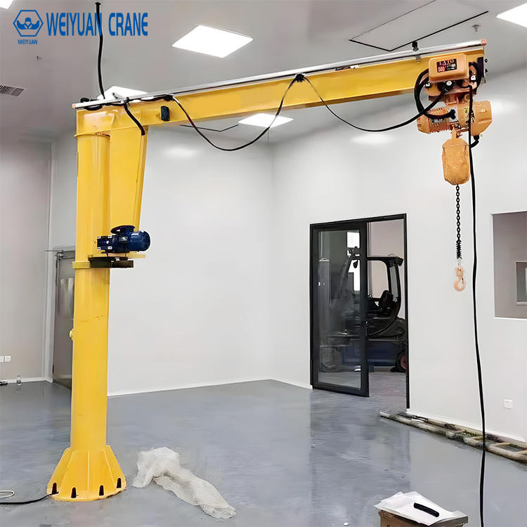
A jib crane foundation failure is not a maintenance problem. It is a structural emergency. When a floor-mounted jib crane mast tilts or its anchor bolts pull from the concrete, the crane becomes an uncontrolled structure. The boom and load can fall without warning. The failure is sudden. It rarely provides time to react.
Most jib crane foundation failures trace back to one of two causes. Either the foundation was designed without understanding the crane’s actual loads — particularly the overturning moment, which is far larger than most people expect. Or the concrete anchor bolts were installed without regard for the edge distance and embedment depth requirements that prevent concrete cone pullout failure.
This guide explains how jib crane foundations actually work. We cover the four load types that govern foundation design. We provide a four-step calculation method. We explain anchor bolt sizing, concrete specification, soil assessment, and wall/column mounting requirements. And we describe the four most common foundation mistakes that cause failures in the field.
Part 1: How Jib Crane Foundations Work — The Forces Involved
A jib crane foundation must resist four distinct force types. Understanding all four is essential. Designing for only the obvious one — the vertical load — produces a foundation that is dangerously under-designed.
Vertical Force — The Obvious Load
The vertical downward force at the mast base equals: crane self-weight + hoist and trolley weight + rated lifted load.
For a 1-ton crane with a 50 kg hoist: total vertical force = approximately 1,100 to 1,300 kg (11 to 13 kN). This seems manageable. It is not the governing load.
Overturning Moment — The Critical Load
The overturning moment is generated by the lifted load acting at a horizontal distance from the mast centerline. It is the product of the load and the boom length.
Overturning moment = load force × boom length
Example: 1-ton crane, 4-meter boom.
Overturning moment = (1,000 kg × 9.81 m/s²) × 4 m = 9,810 N × 4 m = 39,240 N·m ≈ 39 kN·m
For comparison, the vertical force was 13 kN. The overturning moment is equivalent to 39 kN applied at a 1-meter lever arm — approximately three times the vertical load in terms of design impact on foundation size.
This moment is why jib crane foundations are deep, heavy, and significantly larger than people initially expect. The foundation must resist tipping over, not just sinking.
Horizontal Shear Force
Rotation of the boom creates horizontal inertia forces at the mast base. So does emergency stopping of the hoist. ASME B30.12 requires that the dynamic amplification from these effects be included in the design load.
ASME B30.12 specifies a dynamic impact factor of 1.15 for electric hoists. Apply this factor to the total vertical load before calculating the overturning moment. This adds approximately 15% to both the moment and the vertical force used in foundation design.
Fatigue Loading
Jib cranes in production environments perform thousands of lift cycles per year. Each cycle applies and releases the full overturning moment. This cyclic loading accumulates fatigue in the anchor bolts and in the concrete at the bolt holes over the crane’s service life.
For CMAA Class C and above, specify fatigue-category anchor bolts (ASTM F1554 Grade 36 or 55 for most applications) and verify that the anchor bolt stress range under cyclic loading does not exceed the allowable fatigue stress range for the bolt grade. This prevents bolt fatigue fracture — which can occur at loads well below the bolt’s static ultimate strength.
Part 2: Foundation Load Calculation — Four Steps
Work through these steps in order. Use the crane manufacturer’s published foundation load data as the primary input. Do not estimate loads from catalog capacity alone.
Step 1: Determine the Design Load
Design load = (lifted load + hoist and trolley weight) × dynamic impact factor (1.15)
Example: 1-ton crane, standard electric chain hoist weighing 50 kg.
Static load = (1,000 + 50) kg × 9.81 m/s² = 10,301 N ≈ 10.3 kN
Design load = 10.3 kN × 1.15 = 11.8 kN
Step 2: Calculate the Overturning Moment
Overturning moment (M) = Design load × effective boom length
Effective boom length = boom length + distance from mast centerline to mast outer face.
Example: 4-meter boom, 150mm mast radius.
Effective boom length = 4.0 + 0.15 = 4.15 m
M = 11.8 kN × 4.15 m = 49.0 kN·m
Step 3: Calculate Foundation Bearing Stresses
The foundation must distribute the vertical force and overturning moment to the soil beneath it. The combined bearing pressure at the base of the foundation is:
Maximum bearing stress σ_max = N/A + M/W
Where:
N = vertical force (kN)
A = base area of foundation (m²)
M = overturning moment (kN·m)
W = section modulus of base area (m³) = A × D / 6 for a circular base of diameter D
This maximum bearing stress must not exceed the allowable bearing capacity of the soil.
For a 900mm diameter, 1,200mm deep foundation under the 1-ton, 4-meter boom example:
A = π × (0.45)² = 0.636 m²
W = 0.636 × 0.9 / 6 = 0.095 m³
σ_max = (11.8 / 0.636) + (49.0 / 0.095) = 18.6 + 515.8 = 534 kPa
This exceeds typical soil bearing capacity. Increase foundation size or depth to reduce σ_max. This is why jib crane foundations are substantially larger than simple load calculations suggest.
Step 4: Check Against Soil Bearing Capacity
Compare σ_max to the site’s allowable bearing capacity. Typical values:
Soft clay: 50 to 100 kPa
Firm clay: 100 to 200 kPa
Dense sand: 200 to 400 kPa
Gravel and compacted fill: 200 to 600 kPa
Weathered rock: 500 to 1,000 kPa
Sound rock: 1,000 kPa and above
If σ_max exceeds the allowable bearing capacity, options include: increase foundation diameter or depth, use a pile foundation to reach deeper bearing strata, or relocate the crane to a position with better soil conditions.
Always obtain site-specific soil data for cranes above 2 tons or in conditions where soil variability is known. Do not rely on generic table values for critical foundation designs.
Part 3: Anchor Bolt Design
Anchor bolts are the most failure-prone element of a jib crane foundation. They are subject to both high tensile forces (from overturning) and high shear forces (from horizontal loads). They must resist these forces through the concrete that surrounds them — and that concrete can fail in a brittle cone breakout mode if the bolts are too close to the concrete edge or to each other.
Bolt Configuration — Standard Options
Most jib crane manufacturers specify one of these anchor bolt configurations:
Light cranes (250 to 500 kg, boom to 4m): 4 × M24 bolts on a bolt circle of 300 to 400mm diameter.
Medium cranes (500 to 2,000 kg, boom to 6m): 4 × M30 bolts on a bolt circle of 400 to 600mm diameter.
Heavy cranes (2,000 to 5,000 kg, boom to 8m): 4 × M36 or 6 × M30 bolts on a bolt circle of 600 to 800mm diameter.
Always use the crane manufacturer’s specified bolt configuration. These configurations have been engineered for the specific mast base plate geometry and the crane’s published foundation loads. Substituting different bolt sizes without re-engineering the base plate and foundation connection is a structural design error.
Embedment Depth
Anchor bolts must be embedded deep enough in the concrete to develop their full tensile capacity through bond and mechanical anchorage — and deep enough that the concrete cone pullout failure surface does not extend to the top of the foundation or to an adjacent bolt.
Minimum effective embedment depth (h_ef) per ACI 318 Appendix D (now ACI 318 Chapter 17):
h_ef ≥ 10 × bolt diameter for standard cast-in hooked bolts
h_ef ≥ 15 × bolt diameter for straight cast-in bolts without end hooks
Example: M30 bolt (30mm diameter), straight with hook: h_ef ≥ 10 × 30 = 300mm minimum embedment.
In practice, jib crane anchor bolts are typically embedded 400 to 800mm depending on bolt size and foundation loads. The crane manufacturer’s foundation drawing specifies the required embedment — use that value, not the minimum code value.
Edge Distance and Spacing Requirements
Anchor bolt edge distance (distance from bolt centerline to the nearest concrete surface) must be sufficient to prevent concrete breakout failure along the edge. ACI 318 Chapter 17 specifies minimum edge distance as 6 × bolt diameter for cast-in bolts without special reinforcement.
Minimum edge distance: 6 × 30mm = 180mm for M30 bolts.
This means the foundation must have a minimum radius of 180mm beyond the outermost bolt centerline. For a bolt circle of 500mm diameter (250mm radius) with M30 bolts: minimum foundation radius = 250 + 180 = 430mm. Minimum foundation diameter = 860mm.
Minimum bolt spacing (center-to-center) must also meet ACI 318 requirements: typically 6 × bolt diameter minimum.
Chemical Anchors vs Mechanical Expansion Anchors
For post-installed anchors (drilled into existing concrete after the foundation is poured), two anchor types are used:
Chemical (epoxy) anchors: The hole is cleaned and filled with two-component epoxy adhesive. The bolt is inserted and the epoxy cures. Chemical anchors provide high tensile and shear capacity. They are not susceptible to expansion-induced cracking. They are the correct choice for jib crane post-installed anchors at medium and heavy loads. Requires full cure time before loading (typically 24 to 48 hours at 20°C; longer at low temperatures).
Mechanical expansion anchors: The bolt expands against the hole wall by wedging or sleeve expansion. Faster installation than chemical anchors. Lower tensile capacity for the same hole diameter. Susceptible to installation-induced cracking in high-strength concrete. Appropriate only for light-duty cranes (below 500 kg) where post-installed anchors are needed.
For any jib crane above 500 kg with post-installed anchors: specify chemical anchors only. Use the anchor manufacturer’s published design loads for the specific anchor diameter and embedment depth at the concrete’s compressive strength.
Part 4: Concrete Foundation Specification
Foundation Dimensions
Use the crane manufacturer’s published foundation dimensions as the starting point. Verify them against the soil bearing capacity calculation from Part 2 for your specific site conditions.
Typical dimensions by crane capacity (freestanding pillar crane):
250 kg, 3m boom: 500 to 600mm diameter, 700 to 900mm deep
500 kg, 4m boom: 650 to 800mm diameter, 900 to 1,100mm deep
1,000 kg, 4m boom: 800 to 950mm diameter, 1,100 to 1,400mm deep
2,000 kg, 6m boom: 1,000 to 1,200mm diameter, 1,400 to 1,800mm deep
5,000 kg, 6m boom: 1,300 to 1,500mm diameter, 1,800 to 2,400mm deep
These are starting references only. Site-specific soil conditions can require substantially larger foundations.
Concrete Strength
Minimum concrete compressive strength:
North American standard: f’c = 3,000 psi (20.7 MPa) at 28 days.
For heavy cranes or poor soil conditions: f’c = 4,000 psi (27.6 MPa) preferred.
Chinese national standard: C25 minimum (fcu,k = 25 MPa); C30 preferred for cranes above 2 tons.
European standard: C20/25 minimum (characteristic cylinder strength 20 MPa).
Use normal-weight aggregate concrete (unit weight approximately 2,400 kg/m³). Do not use lightweight aggregate concrete for jib crane foundations — its lower stiffness and lower bearing area capacity are incompatible with the high contact stresses at the foundation base.
Reinforcement
The foundation requires: vertical main bars to resist bending from the overturning moment and horizontal ties (stirrups) to confine the concrete against splitting under anchor bolt tension.
Minimum reinforcement (small cranes to 2 tons): 6 to 8 vertical bars at 300mm spacing, 10mm diameter ties at 150mm spacing in the top 400mm of the foundation (the zone of highest anchor bolt tension).
For cranes above 2 tons: engage a structural engineer to design the reinforcement based on the calculated anchor bolt loads and the foundation geometry.
Curing Period
Concrete must reach its design strength before anchor bolt installation loads are applied. The minimum curing period before load application:
Standard curing at 20°C: 28 days.
Accelerated curing (high-early-strength cement, heated enclosure): 7 days minimum — verify with strength testing.
Cold weather curing (below 10°C): extend minimum cure period or use concrete heating provisions.
Do not install the crane or apply any load to the foundation anchor bolts before the concrete has reached its design strength. Premature loading crushes the concrete around the bolt ends and permanently reduces the anchor’s load capacity.
Part 5: Soil Bearing Capacity Assessment
When a Geotechnical Investigation Is Required
A geotechnical soil investigation is required before finalizing any jib crane foundation design in these situations:
Crane capacity above 2 tons at any boom length.
Crane at any capacity in areas with known soft soil, fill material, or variable ground conditions.
Installation in buildings with basement levels, underground structures, or where ground condition history is unknown.
Any location where a previous foundation exists — old footings can create unexpected loading conditions.
What the Investigation Provides
A geotechnical report provides the site-specific allowable bearing capacity at the required foundation depth. This replaces the generic table values used for preliminary design. It also identifies any underground obstacles — buried foundations, utility trenches, rock variation — that affect foundation design.
For a crane above 2 tons, the geotechnical investigation cost ($500 to $2,000 for a standard borehole and report) is minor compared to the cost of a foundation failure or a complete foundation redesign after a failed installation.
Soft Soil Solutions
When the site soil bearing capacity is insufficient for a standard spread foundation:
Enlarged foundation: Increase foundation diameter and depth to reduce bearing stress. Practical limit: approximately 1.8 to 2.0 meters diameter before the excavation and formwork cost becomes prohibitive.
Piled foundation: A short pile (typically 150 to 300mm diameter, 2 to 5 meters deep) transfers the foundation load to deeper, stronger soil strata. The pile is cast integrally with the foundation pad.
Ground improvement: Dynamic compaction or vibro-compaction of granular soils can increase bearing capacity sufficiently to support a standard spread foundation. Not applicable to cohesive (clay) soils.
Part 6: Wall and Column Mounting — Structural Requirements
Wall-Mounted Crane: Upper Bracket Tension Force
The most important load to understand for wall-mounted jib cranes is the upper mounting bracket tension force. This is the horizontal outward pull on the upper mounting bracket.
Upper bracket tension force = overturning moment / vertical distance between upper and lower mounting brackets
Example: 1-ton crane, 4-meter boom. Overturning moment = 49 kN·m (from Part 2). Upper and lower bracket vertical spacing = 1,200mm (typical).
Upper bracket tension = 49 kN·m / 1.2 m = 40.8 kN ≈ 4.2 tons outward pull
A standard office partition wall fails at a fraction of this force. A 200mm thick reinforced concrete wall can typically carry it — but must be verified by a structural engineer using the wall’s actual reinforcement and construction details.
Wall Structural Requirements
The wall must be:
Reinforced concrete or solid brick masonry: Minimum 200mm thickness for light cranes (below 500 kg). Minimum 250 to 300mm for medium cranes (500 to 2,000 kg).
Structurally continuous: The wall must transfer the bracket loads to the building’s primary structure through its own reinforcement or through shear walls and diaphragms. Non-load-bearing infill walls, hollow core block walls, and gypsum board partitions cannot carry any jib crane mounting loads.
Assessed by a structural engineer before installation: The wall’s structural capacity must be verified by calculation or test — not estimated visually. Engaging a licensed structural engineer for a wall capacity assessment before installation is not optional for any wall-mounted crane.
Column-Mounted Crane: Building Column Assessment
A building column used as the mounting structure for a jib crane must carry the crane loads in addition to its original structural loads (roof, floors, wind). The combined load must not exceed the column’s design capacity.
The structural engineer must obtain: the original structural drawings for the building, the column’s original design loads, and the crane’s published mounting loads. Without the original drawings, the engineer must assess the column by inspection and measurement — more expensive and less reliable than working from design drawings.
Provide the engineer with the crane manufacturer’s published foundation load data package. This data — vertical force, overturning moment, horizontal shear — is the specific input required for the mounting structure assessment. Generic load estimates are not acceptable for this calculation.
Part 7: Four Common Foundation Mistakes
Mistake 1: Designing for Vertical Load Only — Ignoring the Overturning Moment
The most dangerous and most common error. A foundation sized only for the vertical load will be grossly under-designed for the actual governing load — the overturning moment.
In the 1-ton, 4-meter boom example: the vertical force is 11.8 kN. The overturning moment is 49 kN·m — equivalent to a 50 kN force at a 1-meter lever arm. A foundation designed for 12 kN vertical load needs to be redesigned for 50 kN-equivalent moment load. The resulting foundation is substantially larger.
This mistake is made most commonly when a facilities team installs a crane without engaging a structural engineer — using only the crane’s rated capacity to size the foundation.
Mistake 2: Loading Concrete Before Full Cure
Installing the crane and beginning operation before the foundation concrete has reached its 28-day design strength permanently damages the anchor bolt zone. Green concrete has approximately 50 to 70% of its design strength at 7 days. The anchor bolt bearing stress can crush the partially cured concrete around the bolt end, reducing the bolt’s long-term pull-out capacity.
The damage is not visible. The foundation appears intact. But its anchor bolt capacity has been permanently reduced — sometimes to below the required design level.
Wait the full 28 days. Or test concrete cores at 7 days to verify strength before proceeding. Document the concrete strength test results.
Mistake 3: Inadequate Anchor Bolt Edge Distance
Anchor bolts installed too close to the concrete foundation edge can cause a brittle cone breakout failure — the concrete pyramid above the bolt tears out along a diagonal plane from the bolt end to the concrete surface.
This failure mode is sudden and complete. The bolt pulls out of the concrete carrying a cone of concrete with it. The mast base plate loses its anchorage. The crane tips.
The minimum edge distance requirement — 6 × bolt diameter from bolt centerline to any free concrete surface — must be respected for every bolt. Verify that the foundation diameter is large enough to maintain this edge distance before ordering the concrete formwork.
Mistake 4: Reusing an Existing Foundation Without Assessment
An old foundation from a previous piece of equipment — a machine tool anchor, a previous crane, a storage rack base — looks like a free head start on a new jib crane installation. It rarely is.
The old foundation may have been designed for a completely different load type (machine vibration, rack dead load). Its concrete may be cracked or carbonated. Its anchor bolts may be corroded or undersized for the new crane. Its soil bearing condition may have changed.
Before using any existing foundation for a jib crane, commission a licensed structural or geotechnical engineer to assess it. The assessment should include: concrete core sampling for strength, anchor bolt pull-out testing, visual inspection for cracking, and review of original foundation design documents if available.

Frequently Asked Questions
Q: Who is responsible for designing the jib crane foundation — the crane supplier or the buyer’s structural engineer?
A: The crane manufacturer provides foundation load data — the forces and moments the crane imposes on the foundation. This data is the input for foundation design. The foundation design itself — dimensions, reinforcement, anchor bolt specification, and adequacy for the specific site conditions — is the responsibility of a licensed structural or civil engineer engaged by the buyer. Do not accept a crane purchase without a foundation load data package. Do not proceed to foundation construction without a structural engineer’s design based on that data.
Q: Can the existing industrial floor slab serve as the jib crane foundation?
A: Only for very light cranes (below 250 kg) in specific circumstances. A standard industrial floor slab (100 to 150mm thick, lightly reinforced) has no capacity for the overturning moment of any practical jib crane. Jib crane foundations are independent reinforced concrete elements that extend below the floor slab, designed specifically for the crane’s loads. The floor slab plays no structural role in the foundation and is typically cored through to reach the required foundation depth.
Q: How do I know if my existing wall can support a wall-mounted jib crane?
A: You need a structural engineer to tell you. Bring the crane manufacturer’s wall mounting load data (upper and lower bracket forces, vertical shear) to a licensed structural engineer. The engineer will review the wall’s construction and reinforcement — either from original building drawings or by inspection — and calculate whether the wall can carry the crane loads with acceptable safety margins. No visual inspection, rule of thumb, or experience estimate is a substitute for this structural calculation.