
Steel Mill Overhead Crane Guide: Critical Ladle & High-Heat Specs That Prevent Failure
Introduction
Steel mill overhead cranes operate in conditions that destroy standard industrial equipment. Ambient temperatures reach 40 to 80°C near furnace areas. Molten metal splashes at temperatures above 1,500°C. Dust and metal particles fill the air continuously. The crane runs around the clock at or near rated capacity.
A crane failure in a steel mill is not just a maintenance problem. It is a safety emergency. A ladle crane that loses its load while carrying molten steel does not produce a downtime report. It produces a catastrophe. Zero tolerance for failure is not a design preference. It is a legal and operational necessity.
This guide covers the complete specification framework for steel mill and metal processing overhead cranes. We explain the unique operating conditions. We detail ladle crane requirements under AISE/AIST standards. We cover scrap handling, coil and slab processing, high-temperature specifications, and the inspection program that sustains safe performance in these extreme environments.
Part 1: Steel Mill Operating Conditions — What Makes Them Different
Extreme Ambient Temperature
Steel mill overhead cranes in furnace bays and casting areas operate continuously at ambient temperatures of 40 to 80°C. This is not peak temperature — it is the sustained operating environment.
At these temperatures, standard mineral-based lubricants thin to near-water consistency. They no longer provide adequate film strength between gear teeth and bearing races. Standard Class F motor insulation approaches its rated temperature limit before adding any motor heating from operation. Standard cable insulation softens and flows.
Every component specification for a steel mill crane must account for this sustained high-temperature baseline. Synthetic lubricants with adequate high-temperature viscosity index, Class H motor insulation, and high-temperature-rated cable compounds are mandatory — not optional upgrades.
Radiant Heat from Molten Metal
Beyond ambient temperature, cranes in furnace tap areas and ladle transfer positions are exposed to intense radiant heat from molten metal surfaces. A 300-tonne steel ladle contains approximately 300 tonnes of metal at 1,600°C. The radiant heat flux at the crane bridge directly above is substantial.
Cranes in these positions require heat shields — steel or refractory-lined panels mounted on the underside of the bridge girder. These shields reflect radiant heat away from the crane’s mechanical and electrical components. Without them, component temperatures in the radiant heat zone significantly exceed the ambient temperature already accounted for in the thermal specification.
Impact Loading from Scrap Charging
Scrap steel handling cranes experience impact loads far beyond static calculations. When a grab bucket drops a multi-tonne load of scrap into a furnace vessel, the force transferred through the hoist rope and crane structure far exceeds the static weight of the scrap. This dynamic amplification from scrap dropping creates fatigue loading that accumulates much faster than smooth loading cycle calculations suggest.
AISE/AIST Technical Report No. 6 (the North American standard for mill-duty cranes) requires explicit impact factor calculation for scrap-handling applications. Impact factors of 1.5 to 2.0 or higher are not unusual for heavy scrap drop applications. These factors must be applied to the structural design and the runway beam design simultaneously.
Continuous High-Duty Cycle Operation
A steel mill ladle crane may perform 15 to 25 complete lift cycles per hour, 24 hours per day, 7 days per week. This is CMAA Class F service — the most demanding classification in the North American standard. FEM M8 is the equivalent European designation.
At this duty intensity, the crane consumes its design fatigue life in 8 to 12 years of service rather than the 20+ years a correctly rated crane in moderate service achieves. The structural design, gearbox sizing, wire rope specification, and brake system must all be engineered for this consumption rate.
Part 2: Ladle Cranes — The Most Critical Steel Mill Overhead Crane
Safety Classification
The ladle crane carries molten steel. A dropped load or runaway descent is immediately life-threatening and capable of catastrophic facility damage. This consequence profile places the ladle crane in the highest safety classification of any industrial overhead crane application.
The ladle crane’s safety requirements go beyond standard ASME B30.2 and CMAA requirements. AISE/AIST Technical Report No. 6 establishes additional design requirements specific to molten metal handling. These include structural redundancy, dual independent hoisting mechanisms, and anti-tipping provisions that have no equivalent in standard industrial crane design.
Typical Capacity and Configuration
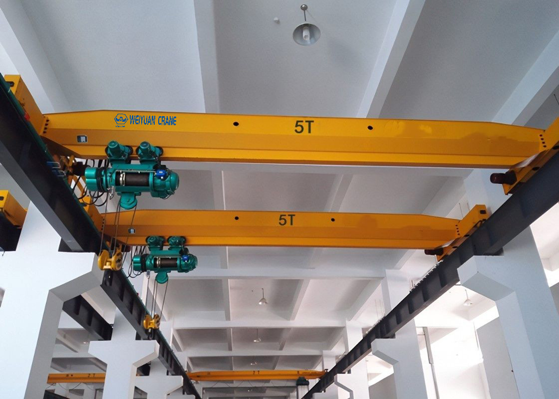
Ladle crane capacity ranges from 50 tonnes for small steelmaking operations to 500 tonnes for large continuous casting lines. The most common configuration in modern steelmaking: 100 to 250-tonne capacity double-girder overhead crane with independent main and auxiliary hoisting mechanisms.
The main hoist carries the full ladle weight. The auxiliary hoist tilts the ladle during tapping or pouring. Both mechanisms must be independently capable of holding the full ladle load without the other. This is the practical implementation of the single-failure-proof design philosophy for ladle cranes.
AISE/AIST Technical Report No. 6 Requirements
AISE (Association of Iron and Steel Engineers, now merged into AIST — Association for Iron & Steel Technology) Technical Report No. 6 is the governing technical standard for mill-duty cranes in North American steelmaking. Its key requirements beyond standard CMAA specifications:
Structural design basis: All structural members must be designed for the combined dead load, live load, impact load, and thermal load simultaneously. The standard specifies explicit load combination factors for each load type.
Dual brake requirement: The hoist must have two independently actuated brakes. Either brake alone must hold 125% of rated load. This is not the same as a single brake with redundant actuator — both brakes must be fully independent mechanical systems.
Anti-tipping device: A mechanical device must prevent the ladle from tipping if the hoist rope goes slack on one side. This device engages automatically and does not rely on the control system or operator action.
Overload protection: Rated at 110% of rated capacity — more conservative than the standard ASME B30.16 125% setting. The tighter limit reflects the catastrophic consequence of overloading a molten metal handling crane.
Heat Protection for the Hoist Mechanism
The hoist mechanism on a ladle crane requires specific heat protection provisions:
Wire rope: High-temperature wire rope with galvanized IWRC and heat-resistant rope lubricant. Standard rope lubricants volatilize at sustained temperatures above 80°C, leaving the rope dry and accelerating corrosion and fatigue.
Hoist drum and sheaves: Heat shielding panels on the hoist body. Distance from the rope’s contact point with the hot ladle to the sheave must be sufficient that the rope cools before entering the drum fleet angle zone.
Electrical components: All electrical equipment on the crane bridge must be rated for continuous operation at the maximum expected ambient temperature plus the temperature rise from self-heating.
Part 3: Scrap Handling Cranes
Operating Profile
Scrap yard and scrap bay overhead cranes handle ferrous and non-ferrous scrap with electromagnetic lifting magnets, grab buckets, and orange peel grapples. The operating profile is demanding in a different way from ladle cranes.
Scrap cranes typically run at 10 to 20 cycles per hour — CMAA Class D to E. Each cycle involves dropping the magnet or grab onto an irregular pile of scrap, picking up an uncontrolled weight of material, and releasing it into a vessel or onto a pile. The load magnitude varies significantly from cycle to cycle. The impact forces from magnet contact and grab closure are substantial.
Structural Reinforcement for Impact
The end truck frames, wheel axle mounts, and bridge-to-end-truck connections of a scrap crane experience higher dynamic forces than an equivalent capacity smooth-load crane. AISE Technical Report No. 6 specifies increased connection weld sizes and end truck section weights for scrap and magnet service. These reinforcements add cost. They prevent the fatigue cracking at end truck connections that becomes expensive to repair once it starts.
Electromagnetic Magnet Specifications
The lifting magnet on a scrap crane is one of the most frequently replaced components. Magnets in continuous scrap service require:
100% duty cycle rating: The magnet must maintain full magnetizing current continuously without thermal runaway. Magnets rated for lower duty cycles will overheat and demagnetize in continuous scrap service.
Fail-safe capacitor backup: A capacitor bank maintains magnetizing current for 30 to 60 seconds after a power interruption. This prevents a full magnet load of scrap from dropping uncontrolled during electrical faults.
Manganese steel wear plate: The magnet’s contact face uses manganese steel — a highly impact-resistant alloy. Standard steel would deform and crack rapidly under repeated scrap contact impacts.
Part 4: Slab and Coil Handling Cranes
Slab Tongs Configuration
Slab and bloom transfer cranes handle continuous casting output — rectangular steel slabs typically 150 to 300mm thick, 1,000 to 2,000mm wide, and 5 to 12 metres long. Weights range from 5 to 40 tonnes per slab depending on dimensions and steel density.
Slab tongs — mechanical grippers that clamp the slab at its ends — are the standard lifting attachment. The crane must position the tongs with sufficient precision to engage the slab ends squarely. Asymmetric tong engagement creates torsional loads on the hoist that standard symmetric loading designs do not account for.
Crane specification for slab service: double-girder overhead crane with VFD control on the hoist and both travel drives. Positioning accuracy: ±20mm for crane travel, ±10mm for hoist positioning during tong engagement.
Coil Handling with C-Hooks
Cold mill, annealing line, and warehouse cranes handle coils of rolled steel strip. Steel coils typically weigh 5 to 35 tonnes and are handled with C-hook lifting devices — a curved beam that engages the coil’s inner diameter.
The C-hook weight is significant — typically 1 to 4 tonnes for the sizes used in steel service. This must be added to the coil weight to determine the crane’s total suspended load.
C-hook handling requires specific positioning requirements. The crane must lower the C-hook into the coil’s inner bore accurately enough for the hook to engage without tilting. Tilt during engagement can damage the coil edge. VFD micro-speed control (0.3 to 0.5 m/min) for the final positioning phase is standard for coil cranes.
Coil stacking operations require repeatable positioning accuracy of ±10 to ±20mm — demanding enough that laser-assisted positioning systems are increasingly specified for high-throughput coil cranes.
Part 5: High-Temperature Technical Specifications
Motor Insulation
Class H insulation is the minimum for steel mill overhead crane motors. Class H is rated to 180°C maximum winding temperature. In a 60°C ambient environment, Class H insulation provides a 120°C temperature rise budget — adequate for sustained operation.
Standard Class F insulation is rated to 155°C maximum winding temperature. In a 60°C ambient, only 95°C of temperature rise is available. For heavy-duty steel mill cycles, motor heating can approach or exceed this limit during sustained operation.
Specify Class H insulation for all motors. Specify continuous-duty motor ratings — not intermittent S3 ratings that assume cooling periods that steel mill production schedules do not provide.
Lubricants
Standard mineral gear oils are adequate to approximately 80°C sustained sump temperature. Above this threshold, viscosity drops below the minimum film thickness required for hydrodynamic lubrication.
Specify: ISO VG 220 or 320 fully synthetic PAO (polyalphaolefin) gear oil for all gearboxes in steel mill service. PAO maintains adequate viscosity at 100°C sump temperature and above. Annual oil sampling — not the standard 2 to 3-year change interval — is appropriate for steel mill thermal conditions.
For hoist wire rope lubrication: specify high-temperature rope lubricant rated for continuous service at the expected rope temperature. Standard rope lubricants liquify and run off at elevated temperatures, leaving the rope dry.
Electrical Cabinet Cooling
Electrical panels on steel mill cranes cannot rely on natural convection cooling. Forced air cooling with filtered air intakes is the standard solution. The filter prevents metal dust entry. The fan maintains positive pressure in the enclosure — keeping dust out through the seams that natural convection cooling leaves at neutral pressure.
Specify: forced air cooling with pre-filter and final filter for all electrical cabinets in steel mill environments. Verify that the fan capacity is sufficient to maintain cabinet interior temperature below 40°C at the maximum expected ambient temperature.
Part 6: Steel Mill Crane Inspection Program
Three-Level Inspection Structure
Steel mill cranes require a more intensive inspection program than standard industrial cranes. The following three-level structure reflects industry best practice for molten metal handling cranes:
Monthly detailed inspection: Full ASME B30.2 frequent inspection plus: electromagnetic brake air gap measurement, wire rope end fitting inspection, all structural bolts torque verification, and hoist limit switch calibration check. Performed by qualified maintenance personnel.
Quarterly engineering review: All monthly inspection items plus: oil sample analysis from all gearboxes, brake spring load measurement, structural crack inspection at primary weld connections, and runway alignment measurement. Performed by a qualified crane engineer.
Annual NDT structural inspection: All items above plus: magnetic particle or dye penetrant testing at all primary weld connections in the load path, ultrasonic testing of the main girder bottom flange in the maximum stress zone, and formal written report by a licensed structural engineer retained in the crane’s permanent record.
The Load Path Concept
A steel plant ladle crane has 12 to 15 major component groups in its load path — the continuous chain of structural and mechanical components that transfers the load from the hook to the building structure. A failure in any single component drops the load.
The load path components are: hook and hook block, wire rope, rope drum, hoist gearbox, hoist motor, drum shaft, drum bearings, bridge girder, end trucks, runway rails, runway beams, and building columns. Each component must be included in the inspection scope. Inspecting only the most visible or most accessible components is not adequate for ladle crane service.
NDT Trigger Conditions
Non-destructive testing (NDT) of structural welds is triggered by any of the following:
The crane has reached 75% of its design fatigue life as calculated from the load spectrum records. The crane has been in service for 10 years in CMAA Class E or F service. Any visual inspection has identified a surface irregularity at a primary weld connection that cannot be definitively classified as a weld defect or a fatigue crack by visual examination alone. The crane has experienced an overload event above 110% of rated capacity.
Do not wait for visible cracks before commissioning NDT. Fatigue cracks propagate rapidly once initiated. A crack that is 2mm long at one inspection can be 20mm long six months later.

Frequently Asked Questions
Q: Does a steel mill overhead crane need to meet different standards than a standard industrial crane?
A: Yes. Steel mill cranes in North America are designed to AISE/AIST Technical Report No. 6 in addition to CMAA Specification No. 70. The AIST standard adds requirements for dual braking systems, anti-tipping devices, higher overload protection conservatism, and specific impact factor calculations for scrap and molten metal service that standard CMAA specifications do not address.
Q: How often should ladle crane wire rope be replaced?
A: In standard industrial service, wire rope is replaced based on ASME B30.16 rejection criteria — typically every 2 to 5 years. In steel mill ladle crane service, replacement intervals are substantially shorter due to heat exposure and high cycle frequency. Most steel mill operators replace ladle crane ropes on a time-based interval of 6 to 18 months regardless of visual condition, supplemented by magnetic rope testing (MRT) to detect internal deterioration not visible externally.
Q: Can a standard CMAA Class D crane be used in a steel mill if the loads are within its rated capacity?
A: Not for ladle service or scrap handling. The CMAA class addresses duty cycle and fatigue. The AIST standard addresses the additional structural redundancy and safety provisions required for molten metal handling. A CMAA Class D crane does not have the dual braking, anti-tipping, or the structural impact factors required by AIST for ladle service — regardless of its rated capacity.