
Top Running vs Under Running Bridge Crane: Runway Structure Differences That Drive Building Cost
Introduction
This decision happens on the building drawings — often before the crane supplier is even selected. And it locks in consequences for the next 20 to 30 years.
Top running and under running are the two fundamental ways a bridge crane connects to its supporting structure. Top running cranes ride on rails mounted on top of runway beams that are themselves supported on brackets projecting from the building columns. Under running cranes hang from the bottom flange of runway beams, traveling along the underside of that flange.
The choice between them affects: how much structural steel the building needs, how much hook height is available within a given building clear height, what crane capacities and spans are practical, and how much room exists to upgrade the crane in the future without rebuilding the structure.
Many of these consequences are difficult or expensive to reverse once the building is built. This guide explains the structural differences, the practical capacity and span ranges for each, the hook height comparison, and the decision framework for choosing correctly at the building design stage.
Part 1: Structural Definitions and Load Paths
Top Running
The crane’s end truck wheels run on top of a rail, which sits on top of the runway beam’s top flange. The runway beam is typically supported on brackets that project horizontally from the building columns — positioning the beam at the elevation required for the crane.
Load path: wheel → rail → top flange → web → beam-to-bracket connection → bracket → column → foundation.
This is the configuration covered by CMAA Specification No. 70, and it is the configuration used for the great majority of industrial bridge cranes across the full range of capacities — from a few tonnes to several hundred tonnes for the largest mill cranes.
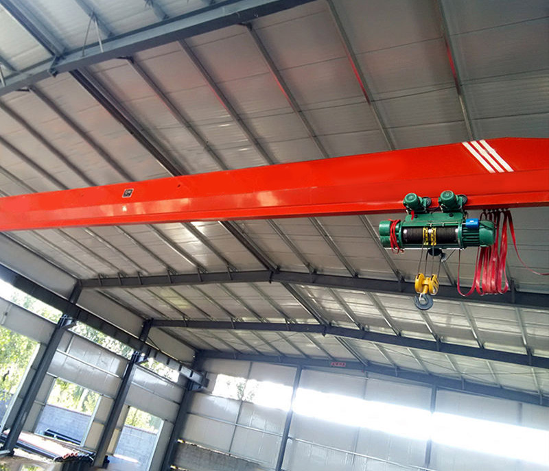
Under Running
The crane’s end truck wheels run on top of the bottom flange of the runway beam, with the end truck structure wrapping around to hang below the beam. The runway beam itself may be a dedicated beam supported between columns, or in some configurations, an extension of the roof structure’s framing members.
Load path: wheel → bottom flange (local bending + torsion) → web → beam-to-column (or beam-to-roof-structure) connection → column or roof structure → foundation.
This is the configuration covered by CMAA Specification No. 74, generally applied to single girder cranes at capacities significantly lower than the top running range.
Part 2: Why the Standards Differ
Top Flange Loading vs Bottom Flange Loading
When a wheel load is applied to the top flange of a beam (top running), the load is applied directly over the web — the flange transmits the load into the web through straightforward bending in the plane of the web. This is the loading condition that standard beam bending theory addresses directly.
When a wheel load is applied to the bottom flange (under running), the load is applied to the flange at a point offset from the web — typically near the flange tip, where the crane’s end truck wheel runs. This creates two additional effects beyond simple bending: local bending of the flange itself (the flange acts like a small cantilever between the web and the load point), and torsion in the beam (because the load is applied eccentrically relative to the beam’s shear center).
CMAA Specification No. 74 includes specific provisions for evaluating this combined local flange bending and torsional stress — a more complex check than the primarily bending-and-shear evaluation that governs top running beam design under CMAA 70.
Why This Limits Under Running Capacity
The combined local bending and torsional stresses in an under running beam’s bottom flange increase rapidly as wheel loads increase. To keep these stresses within allowable limits at higher wheel loads, the bottom flange would need to become very thick and wide — at which point the section becomes inefficient compared to simply switching to a top running configuration, where the load applies directly over the web without the local flange and torsion penalty.
This is the underlying reason under running configurations are generally limited to lighter capacities — typically up to approximately 10 to 15 tonnes for standard under running single girder cranes, though specific limits depend on span, beam section, and the crane manufacturer’s design.
Part 3: Practical Capacity and Span Ranges
Top Running
Capacity: no practical upper limit from the runway structure’s perspective — top running runway beams (including welded plate girders for heavier applications) are used for cranes from a few tonnes to several hundred tonnes.
Span: practical to 35+ metres as standard, with longer spans achievable through deeper welded plate girder sections, as discussed in the companion runway beam design guide.
Under Running
Capacity: practical range up to approximately 10 to 15 tonnes for standard configurations, governed by the combined local flange bending and torsion limits discussed above.
Span: under running spans are generally more limited than top running — typically up to approximately 15 to 20 metres for standard configurations. Beyond this range, the beam depth required to control deflection (the same L/600-type limits discussed in the runway beam design guide apply to under running beams as well) begins to create practical issues: a deeper beam reduces the available hook height (the opposite of under running’s usual headroom advantage, discussed in Part 5), and at some point a top running configuration becomes more efficient for the same span and capacity.
Part 4: Impact on Building Structural Steel
Top Running — Brackets and Dedicated Runway Beams
Top running configurations require: brackets projecting from the columns to support the runway beam at the correct elevation, and a runway beam that is structurally independent from the roof framing — designed specifically for the crane loads as discussed in the companion runway beam design guide.
The brackets add steel to the columns beyond what the columns would otherwise require for building loads alone — and the bracket connection is a fatigue-sensitive detail requiring careful design, as discussed in Part 6 of the runway beam design guide.
The runway beam itself is additional steel, sized specifically for crane loads, independent of the roof structure.
Under Running — Integration with Roof Structure
In some under running configurations — particularly for lighter cranes — the runway beam can be integrated with or supported by the roof structure’s framing members, rather than requiring entirely separate dedicated beams and brackets.
Columns supporting an under running runway typically do not require the projecting brackets that top running requires — the runway beam connects to the column (or to the roof framing) without the bracket’s cantilever projection.
For light-capacity applications where this integration is structurally feasible, the overall additional steel required for an under running system can be less than an equivalent top running system — this is the source of under running’s reputation for lower-cost structural integration at light capacities.
Where the Cost Comparison Reverses
As capacity and span increase toward the upper end of under running’s practical range, the beam depth required for under running (to satisfy both strength and deflection requirements within the local flange bending constraints) grows disproportionately — and at some point, a top running configuration with its independent runway beam and brackets becomes the more steel-efficient solution, even though it requires the additional bracket steel that under running avoids.
The crossover point depends on the specific capacity, span, and building geometry — there is no single capacity value above which top running is “always” more economical. But the general pattern holds: under running’s structural cost advantage is real at light capacities and shorter spans, and diminishes — eventually reversing — as capacity and span increase.
Part 5: Hook Height Comparison
The Headroom Tradeoff
For top running cranes, the trolley and hoist sit on top of the bridge girder — adding the bridge girder depth, plus the runway beam depth, plus the bracket projection height, all between the building’s underside-of-roof-structure elevation and the hook’s maximum height.
For under running cranes, the trolley and hoist hang below the bridge girder — but the runway beam itself (which the crane’s end trucks wrap around) still occupies space between the roof structure and the crane bridge.
Worked Comparison — 9-Metre Clear Height Building
Top running configuration (single girder bridge crane on top running runway):
Building clear height: 9.0m
Less: runway beam depth + bracket: approximately 0.8 to 1.0m
Less: bridge girder depth: approximately 0.5 to 0.7m
Less: hoist headroom (underhung trolley on bridge girder): approximately 0.4 to 0.6m
Available hook height: approximately 6.7 to 7.3m
Under running configuration (single girder bridge crane on under running runway):
Building clear height: 9.0m
Less: runway beam depth (which the end truck wraps around — this depth is “used” by the runway beam itself, but does not add a separate bracket projection): approximately 0.6 to 0.9m
Less: bridge girder depth: approximately 0.4 to 0.6m
Less: hoist headroom: approximately 0.4 to 0.6m
Available hook height: approximately 6.9 to 7.6m
In this comparison, under running provides a modest hook height advantage — roughly 0.2 to 0.3m — primarily because it avoids the separate bracket projection that top running requires.
Why This Advantage Disappears at Longer Spans
As discussed in Part 3, under running beam depth must increase with span to control deflection — and because under running beam depth is directly “in the way” of hook height (the end truck wraps around this beam), an under running configuration at a longer span can require a beam deep enough that its hook height advantage disappears or reverses compared to a top running configuration, where the runway beam depth is less directly coupled to the hook height calculation (the bridge girder sits on top of the rail, somewhat independent of the runway beam’s own depth, within limits).
For any specific project where hook height is a critical constraint, calculate the available hook height for both configurations using the actual beam depths from the structural design — do not rely on a general rule of thumb once span and capacity move toward the upper end of under running’s practical range.
Part 6: Decision Framework
Choose Top Running When:
Capacity exceeds approximately 10 to 15 tonnes — at this point, under running’s local flange bending and torsion limits become the binding constraint.
Span exceeds approximately 15 to 20 metres — under running beam depth requirements begin working against its headroom advantage.
Future capacity upgrades are anticipated — top running runway beams and brackets, designed with reasonable margin, can often accommodate a crane capacity upgrade within the same structure; under running systems near their capacity limit have little room for upgrade without structural replacement.
The application involves heavy-cycle, high-duty-class service (CMAA Class D and above) — top running’s well-established fatigue detailing for bracket connections under CMAA 70 is the more mature design framework for high-cycle applications at any meaningful capacity.
A double girder configuration is required — double girder cranes are inherently top running.
Choose Under Running When:
Capacity is at or below approximately 10 tonnes, and span is at or below approximately 15 to 20 metres.
Budget is constrained, and the lighter-capacity structural integration advantage applies to the specific building geometry.
Hook height is critical and the calculation (performed for the actual beam depths required) confirms under running’s modest headroom advantage holds for this specific span and capacity.
The application is light-duty, intermittent use (CMAA Class A-C) — within under running’s well-established range for this duty profile.
Part 7: 2026 Structural Cost Reference
These figures represent the additional structural steel cost (runway beams, brackets or roof integration, and any additional column capacity) for the crane-served bays, compared to an equivalent building with no crane — for a representative 5-tonne, 15-metre span application.
Top running configuration (dedicated runway beam + column brackets):
Additional structural steel cost: representative range for the crane-served bays, reflecting the runway beam, bracket fabrication and installation, and any additional column reinforcement for combined loads.
Under running configuration (runway beam integrated with or supported by roof structure, no separate brackets):
Additional structural steel cost: typically lower than the top running figure for this capacity and span range — reflecting the avoided bracket fabrication and the potential for roof structure integration.
At this capacity and span (5 tonnes, 15m), under running’s structural cost advantage is typically in the range of 15 to 25% lower than top running for the crane-served structure.
Future Upgrade Cost
If a building is constructed with an under running system at or near its practical capacity limit, and a future capacity upgrade beyond that limit becomes necessary: the under running runway beams and their connections to the roof structure typically cannot be reused — the upgrade effectively requires installing a new top running runway system (beams and brackets) within the existing building, working around the existing roof structure and any existing under running components that must be removed.
This retrofit is significantly more expensive than the incremental cost would have been to specify top running at the original construction stage — frequently several times the original structural cost difference between the two options. For buildings where any reasonable possibility of future capacity growth exists, this asymmetry favors specifying top running from the outset, even at the modest cost premium for current requirements.
Frequently Asked Questions
Q: Our current need is 5 tonnes, well within under running range. Is there any reason to choose top running anyway?
A: The primary reason is future flexibility. If there is any reasonable likelihood that capacity requirements will increase over the building’s life — new product lines, heavier equipment, process changes — specifying top running from the outset avoids the substantial retrofit cost of converting from under running to top running later, as discussed in Part 7. If the 5-tonne requirement is firmly fixed for the building’s entire service life (a genuinely stable, well-defined application with no reasonable growth scenario), under running’s cost advantage at this capacity is a legitimate basis for selection.
Q: Can a single building have both top running and under running cranes in different bays?
A: Yes. There is no requirement for consistency across a building — different bays can be designed for whatever crane configuration suits that bay’s specific application, capacity, and span requirements. This is common in facilities with varied production areas — for example, a heavy fabrication bay with a top running double girder crane, and an adjacent lighter assembly bay served by an under running single girder crane integrated with that bay’s roof structure.
Q: Does the choice between top running and under running affect the crane’s purchase price, separate from the building structural cost?
A: Yes, though the effect is generally smaller than the structural cost difference. Under running single girder cranes are generally less expensive than top running cranes at the light capacities where both are practical options — this is consistent with the broader single girder vs double girder cost relationship discussed in our companion comparison guide (under running cranes are inherently single girder configurations). However, the structural cost difference for the runway and building — which can be 15 to 25% of the crane-served structure’s cost as discussed in Part 7 — is typically the larger factor in the overall project cost comparison between the two configurations.