


Overhead Crane Installation Guide: Step-by-Step Process, Commissioning, and Common Mistakes
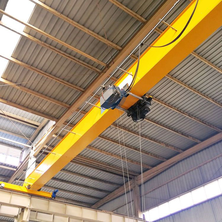
Introduction
An overhead crane can be perfectly engineered and still fail in service — because the failure was built in during installation, not design. A runway rail left 4mm out of level, a bolt group torqued by feel instead of specification, a control panel commissioned in a rush before the safety devices were tested. None of these show up on day one. They surface months later as uneven wheel wear, nuisance trips, and a crane that never quite runs the way the drawings promised.
Installation is where the engineering either comes to life or quietly starts to unravel. It is also the phase where the most avoidable, most expensive mistakes get made — because the pressure to get the crane running competes with the discipline to get it right.
This guide walks through the complete installation and commissioning process from a procurement manager’s and facility engineer’s point of view. You will learn how to prepare the site and run pre-installation checks, how to align the runway and install the rail, how to sequence the crane erection and rigging safely, how to connect and commission the electrical system, how to load test and hand over the crane, and the installation mistakes that cause long-term performance problems. By the end, you will know what a correct installation looks like — and how to hold your installer to it.
This is article 3 of 3 in the Weiyuan Crane overhead crane series. Where article 1 covered OSHA safety compliance and article 2 covered how to buy the right crane, this one covers how to install it so it performs for decades.
Part 1: Site Preparation and Pre-Installation Checks
Everything that goes wrong later is cheaper to fix before the crane arrives. Site preparation is where you confirm the building, the runway supports, and the logistics are actually ready — not assumed to be.
Verify the Building Structure
The crane imposes real loads on your building, and those loads must land where the design expects them. Before anything is lifted:
- Confirm the structural assessment is closed out. The columns, foundations, or roof steel must be verified to carry the crane’s dead weight plus rated load plus dynamic forces at each support point.
- Check that any reinforcement is complete. If the buying phase identified column strengthening or new brackets, confirm the work is finished and signed off before installation begins.
- Verify foundation curing. New concrete foundations or column bases must have reached their design strength before they carry any crane load.
Confirm Dimensions Against the Drawings
Buildings are rarely built exactly to drawing. Measure the real span, the runway support elevations, and the clear height, then compare them against the approved crane drawings. A span that differs from the design by even a few centimetres changes the crane’s wheel gauge and must be resolved before the bridge arrives — not discovered when the wheels do not fit the rails.
Plan Access and Lifting Logistics
The crane arrives in large, heavy sections. Before delivery day:
- Confirm the delivery route, crane-lift access, and a mobile crane or lifting method sized for the heaviest bridge or girder section.
- Identify a safe laydown and assembly area near the runway.
- Plan the lift path for raising each section onto the runway without fouling the building structure.
Pre-Installation Inspection of Delivered Components
When the crane arrives, inspect it before installation, not after. Check the girders, end trucks, hoist, trolley, control panel, rails, and fixings against the packing list and the drawings. Look for transit damage — bent flanges, damaged paint, dented enclosures — and confirm all bolts, clips, and connection hardware are present. A missing bag of rail clips discovered mid-installation stops the whole job.
Takeaway: Site preparation is verification, not paperwork. Confirm the structure, the real dimensions, the access, and the delivered parts before the first lift — every gap closed here is a delay and a cost avoided later.
Part 2: Runway Alignment and Rail Installation
The runway is the foundation the entire crane runs on. Get it aligned within tolerance and the crane tracks straight and wears evenly for decades. Get it wrong and you lock in flange wear and uneven loading from the first day the crane moves.
Establish the Survey Baseline
Before touching a rail, survey the runway beams with an optical level or laser. Establish reference lines for both gauge (the span between the two rails) and elevation along the full runway length. Every rail-setting decision references this baseline.
Set and Align the Rails
Install the rails onto the runway beams, then align them to the crane’s specified tolerances. The critical checks come from CMAA Specification No. 70:
- Track gauge: the span between rail centrelines must sit within ±3mm of nominal at any point.
- Elevation difference between the two rails at any cross-section: ±10mm maximum.
- Straightness (horizontal, individual rail): ±2mm in any 10-metre length.
- Waviness (vertical, individual rail): ±2mm in any 10-metre length.
- Rail joint step: no more than 0.5mm vertical step at any joint.
Shim, adjust, and re-survey until every measurement falls within tolerance. This is slow, exacting work — and it is the single most important step in the whole installation.
Anchor the Rail Correctly
The rail must be clamped against vertical and lateral movement while still free to expand and contract with temperature. Use a clip anchoring system, not a rigid weld to the beam:
- Set clip spacing to the design interval (commonly 600 to 750mm indoors).
- Torque the clips to specification so they grip the rail foot consistently.
- Never weld a running crane rail solid to the beam — a fixed rail buckles under thermal expansion within a few seasons.
Finish the Rail Joints
At every rail joint, check the vertical step with a straight edge and feeler gauge. Grind any step exceeding 0.5mm before the crane runs. An uncorrected joint step becomes a hammer blow on every pass, wearing the wheel and cracking the foundation below it over time.
Document the As-Installed Survey
Record every gauge, elevation, straightness, and joint reading in a runway survey report. Retain it permanently — it is your as-installed baseline for every future alignment check and a key compliance record.
Takeaway: Align the runway to CMAA tolerances before the crane is mounted. Correcting alignment now is straightforward; correcting it after a multi-tonne crane sits on the rails costs many times more.
Part 3: Crane Erection and Rigging Sequence
With the runway aligned, the crane itself goes up. This is the highest-risk phase of the whole installation — heavy sections lifted overhead, people working at height, and a strict sequence that must be followed to keep everyone safe and the crane square.
Plan the Lift
Before any section leaves the ground, confirm the lift plan: the mobile crane capacity, the rigging points, the sling angles, and the exclusion zone below. Every section has designed lifting points — use them, and never improvise a pick from a convenient edge. Assign a qualified signaler and brief the whole team on the sequence.
Assemble on the Ground Where Possible
Wherever access allows, pre-assemble sub-components at ground level rather than at height. On a double girder crane, connect the girders to the end trucks and fit the walkways on the ground, so the bridge goes up as one squared, bolted assembly. Ground assembly is safer, faster, and far easier to align than working piece by piece in the air.
Lift the Bridge onto the Runway
Raise the assembled bridge and set it onto the runway rails. As it lands:
- Confirm the end truck wheels seat correctly on both rails.
- Check the bridge is square to the runway — diagonal measurements should match.
- Verify the wheel flanges sit within the design clearance on both rails.
A bridge that lands out of square skews down the runway and wears its flanges from day one, so squareness is confirmed here, not assumed.
Torque the Structural Connections
Every bolted connection — end truck to girder, splice joints, bracket fixings — must be tightened to the specified torque, not “as tight as it feels.” Use a calibrated torque wrench and the manufacturer’s torque figures. Slip-critical connections must be brought up to full specification, because a loose bolt group works under cyclic load and fatigues the joint. Mark each checked bolt so nothing is missed.
Fit the Trolley and Hoist
Mount the trolley and hoist onto the bridge. On a double girder crane, confirm the trolley wheels seat correctly on the top-mounted trolley rails and run freely across the full bridge length. Check that the hoist is secure and the rope or chain feeds cleanly without twist.
Takeaway: Erection is a sequenced, engineered lift — not a rush job. Pre-assemble on the ground, confirm the bridge lands square, and torque every connection to specification. A crane that goes up square and tight stays reliable; one forced together crooked never fully recovers.
Part 4: Electrical Connection and Control Panel Commissioning
A mechanically perfect crane still does nothing until the electrical system is connected and commissioned correctly. This phase powers the crane and — just as importantly — proves that it stops safely when it must.
Connect the Power Supply
Connect the runway power supply — conductor bar, festoon cable, or cable reel — to the crane’s collectors or feed point. Before energizing:
- Confirm the supply voltage and phase match the crane’s rating.
- Check the conductor bar or festoon is aligned so the collectors run cleanly along the full travel length.
- Verify voltage drop is within limits at the far end of travel under load, especially on long runways.
Earthing and Bonding
Bond the crane bridge, end trucks, runway rails, and control panel to a common earth per the applicable electrical code. Verify continuity across every bonded point. Proper earthing protects against shock if a fault energizes the structure and keeps stray currents from disrupting the control electronics — skip it and you invite both a hazard and maddening intermittent faults.
Commission the Control Panel
Power up the control panel and work through the commissioning sequence:
- Confirm phase rotation. A phase-reversal relay should stop the crane if the rotation is wrong, so motions run in the correct direction.
- Check every motion. Test hoist up/down, trolley left/right, and bridge travel for correct direction against the pendant or remote labels. A reversed control is a serious hazard.
- Verify VFD settings. Where variable frequency drives are fitted, confirm acceleration and deceleration ramps, speed settings, and slow-speed positioning behave as specified.
- Test the enclosure and connections. Confirm the panel enclosure is sealed to its IP rating and all terminations are tight.
Prove the Safety Devices
No crane is handed over until every safety device is tested and proven. This is not optional and never rushed:
- Upper limit switch: confirm it stops the hoist before two-blocking — and test the backup final limit where fitted.
- Overload limiter: verify it prevents lifting beyond the set threshold.
- Emergency stop: confirm the hardwired e-stop drops all motion instantly and requires a deliberate reset.
- Travel limits: check trolley and bridge limits slow and stop the motions before the bumpers contact the end stops.
- Warning devices: confirm the horn, motion alarms, and any beacons work.
Log every safety device test with a result and a date.
Takeaway: Electrical commissioning is where the crane becomes safe to use, not just able to move. Match the supply, bond the structure, prove every motion runs the right way, and confirm every safety device works — before a load ever leaves the ground.
Part 5: Load Testing and Handover
Load testing is the final proof that the crane performs as designed and is safe to release into service. Handover is where you confirm — on paper and on the floor — that everything the contract promised has been delivered.
Perform the Load Test
Before the crane enters service, it must be load tested. Per the governing standards, the test load must not exceed 125% of the crane’s rated capacity unless the manufacturer specifies otherwise. Work through the test methodically:
- No-load functional test first. Run every motion through its full range unloaded to confirm smooth operation, correct limits, and brake holding.
- Rated load test. Lift the rated capacity and confirm the hoist, brakes, and travel motions handle it correctly, with the brake holding the load without drift.
- Overload test to 125%. Lift the test load, confirm the structure and mechanisms perform, and check the brake holds. Inspect for any deflection or distress.
- Record the results. Document the test load, the date, and the outcome, signed by the qualified person. This certified record is central to your compliance file.
Run the Handover Checklist
A structured handover protects you from inheriting an incomplete installation. Confirm and document each item:
- Runway survey report — as-installed alignment within CMAA tolerances.
- Structural connection record — all bolts torqued to specification and marked.
- Electrical commissioning record — motions, phase rotation, VFD settings, and earthing verified.
- Safety device test log — every device tested and proven.
- Load test certificate — dated, signed, capped at 125%.
- Rated load markings — legible on both sides of the crane and on each hoist.
- Documentation pack — operating manuals, maintenance schedule, spare parts list, and as-built drawings.
- Operator familiarization — the installer walks your designated operators through the controls, functions, and safety devices.
Confirm the Baseline for Maintenance
The as-installed records are not just a handover formality — they are the baseline your maintenance program measures against. File the runway survey, the load test certificate, and the commissioning records together. Future inspections compare against these to catch drift before it becomes damage.
Takeaway: Do not accept the crane until it has passed a documented load test and every handover item is signed off. A complete handover pack is your proof the installation was done right — and your starting point for keeping it that way.
Part 6: Common Installation Mistakes That Cause Long-Term Problems
Most cranes that give trouble were installed with a handful of avoidable errors. These are the ones that cost facilities the most over the crane’s life.
Mistake 1: Skipping the Runway Alignment Survey
The rails are set by eye or to rough measurements, and the crane is mounted on a runway that is out of tolerance. The crane tracks crooked, the flanges rub, and the wheels wear out in a fraction of their expected life.
Prevention: survey the runway to CMAA tolerances and correct every out-of-tolerance point before mounting the crane. Never let installation pressure shortcut this step.
Mistake 2: Torquing Bolts by Feel
Structural connections are tightened without a calibrated torque wrench or the specified figures. Under cyclic load, the loose or over-tight bolts work, the joint fatigues, and cracks appear at the connections within a few years.
Prevention: torque every structural bolt to the manufacturer’s specification with a calibrated wrench, and mark each one as it is checked.
Mistake 3: Welding the Rail Rigidly to the Beam
The rail is welded solid to the runway beam instead of clamped with clips. Thermal expansion has nowhere to go, so the rail buckles into humps and lifts off the beam over a few seasons.
Prevention: always anchor the rail with a clip system that grips it while allowing longitudinal thermal movement.
Mistake 4: Commissioning the Crane Before Testing Safety Devices
The crane is released into service because it moves, before the upper limit, overload limiter, and e-stop are proven. The protection is missing exactly when it is first needed.
Prevention: test and log every safety device during commissioning, and hand over no crane until each one is proven to work.
Mistake 5: Ignoring Voltage Drop on a Long Runway
The power supply is connected without checking voltage at the far end of travel. The crane at the end of a long runway runs sluggishly, the motor draws high current, and it overheats over time.
Prevention: calculate and confirm voltage drop under load at the farthest travel point, and add feed points or larger conductors where needed.
Mistake 6: Mounting a Bridge That Landed Out of Square
The bridge is bolted down without confirming it is square to the runway. The crane skews on every travel run, grinding its flanges against the rail from the first shift.
Prevention: check diagonal measurements and flange clearance as the bridge lands, and correct squareness before the connections are finalized.
Mistake 7: Accepting Handover Without Documentation
The crane is put to work with no runway survey, load test certificate, or commissioning records. When a problem appears later, there is no baseline to diagnose against and no proof the installation was compliant.
Prevention: insist on a complete, signed handover pack before accepting the crane, and file it as your maintenance and compliance baseline.
Takeaway: almost every long-term installation problem traces back to a skipped survey, an untorqued bolt, a rigid rail, an untested safety device, or a missing document. Close those gaps and you close most of your future trouble.
Frequently Asked Questions
Q: How long does it take to install an overhead crane?
It depends heavily on the crane’s size, the runway condition, and site access. A standard single girder crane on a prepared runway may be installed and commissioned in a few days, while a large double girder crane requiring runway alignment, structural work, and extensive commissioning can take several weeks. The biggest variables are runway alignment time and whether the building structure and foundations are fully ready. Thorough site preparation is the single best way to keep the installation on schedule.
Q: What alignment tolerances must the runway meet before mounting the crane?
Per CMAA Specification No. 70: track gauge within ±3mm of nominal, elevation difference between the two rails within ±10mm at any cross-section, individual rail straightness within ±2mm in any 10 metres, waviness within ±2mm in any 10 metres, and rail joint steps no greater than 0.5mm. Survey the runway and correct every out-of-tolerance point before the crane is mounted, because fixing alignment after the crane sits on the rails costs many times more.
Q: Why can’t the crane rail simply be welded to the runway beam?
Because the rail expands and contracts with temperature. If it is welded solid, that thermal movement has nowhere to go, so the rail develops compressive stress and buckles into humps over a few seasons, lifting off the beam. A clip anchoring system solves this: the clips grip the rail foot firmly against vertical and lateral movement while still allowing it to slide longitudinally as it expands and contracts. Always use clips for a running crane rail, never a rigid weld.
Q: What is a load test and why is it required at installation?
A load test proves the crane can safely lift its rated capacity before it enters service. The test load must not exceed 125% of the rated capacity unless the manufacturer specifies otherwise, and it verifies the hoisting mechanism, brakes, limit switches, and travel motions under real load. It confirms the installation is sound and the crane performs as designed. The test result must be recorded, dated, and signed as a certified compliance record and a maintenance baseline.
Q: Which safety devices must be tested during commissioning?
At minimum: the hoist upper limit switch (and any backup final limit) to prevent two-blocking, the overload limiter to prevent lifting beyond the set threshold, the emergency stop to confirm it drops all motion instantly, the trolley and bridge travel limits, and the warning devices such as the horn and beacons. Phase rotation and brake holding must also be verified. Every device should be tested and logged during commissioning, and no crane should be handed over until each one is proven.
Q: What should be included in the installation handover package?
A complete handover pack includes the as-installed runway survey report, the structural connection torque record, the electrical commissioning record (motions, phase rotation, VFD settings, earthing), the safety device test log, the signed load test certificate, confirmation of legible rated-load markings, the documentation pack (operating manuals, maintenance schedule, spare parts list, and as-built drawings), and evidence of operator familiarization. These documents prove the installation was done correctly and form the baseline your maintenance program measures against.
Q: Can we install an overhead crane on an existing building, or does it need reinforcement?
It depends on the building. A top-running crane loads its columns and foundations, while an underhung crane loads the roof structure. Before installation, a structural assessment must confirm the building can carry the crane’s dead weight plus rated load plus dynamic forces at each support point. Where the existing structure cannot, you either reinforce it or install a freestanding crane support structure. This should be resolved during the buying phase so the reinforcement is complete before installation begins, not discovered on site.
Q: Should the crane supplier or a separate contractor handle installation?
There are real advantages to having the crane’s manufacturer or its authorized installer handle installation and commissioning. They know the crane’s torque specifications, commissioning sequence, and safety device settings, and they can take responsibility for the whole delivery from design through handover. A separate contractor can work well, but only with full access to the manufacturer’s installation and commissioning documentation. Whichever route you choose, confirm the installer is experienced with cranes of similar capacity and duty, and insist on a documented handover.