


Electric Hoist Installation, Commissioning, and Maintenance Guide: A Complete Technical Handbook
Introduction
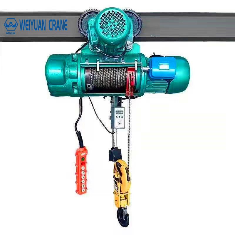
An electric hoist can be perfectly specified and still fail in service — because the failure was built in during installation, not selection. A trolley clamped to the wrong flange width. A brake never tested before the first load. A limit switch left unproven until the day the hook two-blocked into the drum. None of these show up on day one. They surface weeks or months later as a slipping brake, a chain that jumps its lift wheel, or a motor that trips halfway through a lift.
The hoist is the part of your lifting system that does the actual work, cycle after cycle. How well it is installed, commissioned, and maintained decides whether it quietly lifts for 15 years or becomes a recurring source of downtime and risk. And because a hoist works closer to the load than any other component, a shortcut here shows up as a safety problem, not just a maintenance one.
This guide walks through the complete installation, commissioning, and maintenance framework for electric hoists from an engineering and facility-management point of view. You will learn how to prepare the site and structure, how the mounting types differ, how to connect the power supply correctly, how to commission and load test the hoist step by step, what the ASME B30.16 requirements demand, how to build a preventive maintenance schedule with real inspection intervals, and the installation and maintenance mistakes that cost facilities the most. By the end, you will know what a correct hoist installation and maintenance program looks like — and how to hold your installer and your team to it.
This is article 3 of 3 in the Weiyuan Crane electric hoist series. Where article 1 covered safety and OSHA compliance and article 2 covered how to buy the right hoist, this one covers how to install, commission, and maintain it so it performs for years.
Part 1: Site and Structure Preparation
Everything that goes wrong later is cheaper to fix before the hoist is mounted. Site preparation is where you confirm the supporting structure, the dimensions, and the delivered parts are actually ready — not assumed to be.
Verify the Supporting Structure
An electric hoist, plus its rated load and the dynamic forces of lifting, all pass into whatever it mounts to. That structure must be verified before anything is hung from it:
- Fixed mounting point: confirm the beam, bracket, or padeye is rated for the hoist’s dead weight plus the rated load plus dynamic impact.
- Monorail or jib boom: confirm the beam flange can carry the concentrated wheel loads of the trolley at every position along its travel.
- Bridge crane girder: confirm the girder and trolley rails are sized for the hoist and its load at the worst-case position.
A beam adequate for a distributed load is not automatically adequate for the concentrated point load a hoist trolley delivers. Where the check is inconclusive, resolve it before installation, not after.
Confirm the Dimensions Against the Drawings
Buildings and beams are rarely built exactly to drawing. Measure the real beam flange width, the clear height, and the available headroom, then compare them against the hoist and trolley specification. A trolley sized for a 150 mm flange will not clamp a 180 mm one — and that mismatch stops the installation cold if it is discovered on site.
Check the Headroom and Lift Height
Confirm the hook height you actually get once the hoist and trolley are mounted. The hoist body and trolley consume vertical space that reduces lift height, so verify the real hook travel against what the application needs. Where clearance is tight, confirm the low-headroom design was specified — recovering that height after installation is not an option.
Inspect the Delivered Components
When the hoist arrives, inspect it before installation, not after. Check the hoist body, trolley, hook, load chain or wire rope, pendant or remote, and mounting hardware against the packing list and drawings. Look for transit damage, and confirm every bolt, clip, and fitting is present. A missing bag of trolley hardware discovered mid-installation stops the whole job.
Takeaway: Site preparation is verification, not paperwork. Confirm the structure, the real dimensions, the headroom, and the delivered parts before mounting — every gap closed here is a delay and a cost avoided later.
Part 2: Mounting Types and Their Requirements
How a hoist mounts shapes the installation, the trolley you fit, and what the structure must carry. Three mounting arrangements cover nearly all electric hoist installations.
Fixed Mounting
The hoist is bolted in one position — common on simple single-point lifting stations and some jib cranes. No trolley is required, and the installation is at its simplest: the hoist hangs from a rated beam, bracket, or padeye and lifts straight up and down.
Installation focus: confirm the mounting point is rated and the hoist hangs square, so the load lifts vertically without any tendency to swing. Torque the mounting bolts to specification.
Best for: applications where the load never needs to move horizontally.
Monorail (Single-Beam) Trolley Mounting
The hoist rides a trolley along a single fixed beam, moving loads in a straight line — standard on monorails, jib crane booms, and KBK systems. The trolley type must match the duty:
- Plain (push) trolley: moved by hand, for light loads and short travel.
- Geared trolley: hand-chain operated, for more control at moderate loads.
- Motorized trolley: powered travel, for heavier loads, longer travel, or frequent cycling.
Installation focus: confirm the trolley matches the beam flange width, adjust it to the correct clearance so it runs freely without excessive side play, and fit end stops at both ends of the beam. Push or run the trolley through its full travel and confirm smooth movement with no binding.
Bridge Crane Trolley Mounting
The hoist rides a trolley across the bridge girder while the bridge travels the runway, giving full rectangular coverage of a bay — the standard on overhead and gantry cranes.
Installation focus: confirm the trolley wheels seat correctly on the trolley rails and run freely across the full bridge length. Where clearance is tight, confirm a low-headroom trolley protects the hook height. Verify the trolley travels without skew and the wheel flanges sit within clearance on both rails.
Whatever the mounting, confirm the trolley type, the beam flange width, and any headroom constraint before finalizing the installation.
Takeaway: Match the mounting and trolley to how the load must move — fixed for one point, monorail for a line, bridge crane for a bay — and confirm the trolley fits the beam and runs freely before adding any load.
Part 3: Electrical Connection and Power Supply Requirements
A mechanically mounted hoist does nothing until the electrical system is connected correctly — and it does nothing safely until that system is proven. This phase powers the hoist and sets up the commissioning that follows.
Match the Supply to the Hoist
Before connecting anything, confirm the incoming supply matches the hoist’s rating:
- Voltage and phase: the supply voltage and number of phases must match the hoist nameplate exactly. A mismatch damages the motor or prevents operation.
- Frequency: confirm the supply frequency matches the hoist rating, since it affects motor speed and performance.
- Full-load current: confirm the supply and its protection are sized for the hoist’s full-load current plus starting current.
Size the Power Supply and Check Voltage Drop
On a traveling hoist, power reaches the moving unit through a festoon cable system, a conductor bar, or a cable reel. Size the conductor for the hoist’s full-load current, then check the voltage drop at the farthest point of travel under load. Keep the total voltage drop within about 5%, because a sagging voltage at the end of a long run makes the motor draw higher current, run hot, and lift sluggishly. Long runways may need feed points at both ends.
Route the Cabling Cleanly
Route the festoon or trailing cable so it follows the trolley and bridge travel without dragging, stretching, or snagging at the extremes of movement. Keep the minimum bending radius above the cable manufacturer’s limit to avoid fatigue at the flex points. Poorly routed cable is one of the most common sources of nuisance faults on a traveling hoist.
Earth and Bond the System
Bond the hoist body, trolley, beam or structure, and any control enclosure to a common earth per the applicable electrical code, and verify continuity across every bonded point. Proper earthing protects against shock if a fault energizes the structure and keeps stray currents from disturbing the controls. Skip it and you invite both a hazard and maddening intermittent faults.
Confirm the Enclosure Rating
Confirm the hoist and panel enclosure match the environment’s IP rating — IP54 for clean indoor bays, IP65 or higher for dusty, damp, or outdoor conditions. An under-rated enclosure lets dust and moisture reach the electrics, causing corrosion and intermittent faults.
Takeaway: Match the supply to the nameplate, size the conductor and check voltage drop, route the cabling for full travel, and bond the whole system to earth before energizing anything.
Part 4: Commissioning Step by Step
Commissioning is where the hoist becomes safe to use, not just able to move. Work through the sequence in order — each step confirms the hoist responds correctly and stops safely before it ever carries a load.
Step 1: Confirm Phase Rotation and Motion Direction
Power up and check that every motion runs in the correct direction against the pendant or remote labels. On a three-phase supply, a reversed phase makes the hoist run backward — pressing “up” lowers the load, a serious hazard. Where a phase-reversal relay is fitted, confirm it stops the hoist on a wrong or missing phase. Test hoist up and down, and trolley or bridge travel, against their labels, and correct any reversed motion before going further.
Step 2: Test the Limit Switches
The limit switches stop each motion before it reaches a damaging end:
- Upper limit: run the hook up slowly and confirm it stops before the hook block two-blocks into the drum or lift wheel. Where a backup final limit is fitted, test it separately.
- Lower limit: run the hook down and confirm it stops with enough rope wraps left on the drum, or enough chain, at full lower.
- Travel limits: where fitted, confirm the trolley and bridge slow and stop before the end stops.
The upper limit is the device that prevents a two-block event that can snap the rope and drop the load — test it carefully and never bypass it.
Step 3: Test the Brake
Confirm the holding brake sets the instant the motor stops and holds the load without drift. With a test load raised and held stationary, watch for any downward creep. A brake that lets the load drift is either worn, misadjusted, or contaminated — resolve it before the hoist enters service.
Step 4: Test the Overload Device
Where an overload device is fitted, confirm it prevents lifting beyond its set threshold, typically 100 to 110% of rated capacity. Apply a load above that threshold and confirm the device cuts the lift command. This backstop protects the hoist, the rope or chain, and the structure from overload — verify it works rather than assuming it does.
Step 5: Confirm the Controls and Warning Devices
Confirm the pendant or remote responds correctly on every button, the emergency stop drops all motion instantly and requires a deliberate reset, and any horn, alarm, or beacon works. Where VFD control is fitted, confirm the acceleration and deceleration ramps, speed settings, and slow-speed positioning behave as specified.
Log every commissioning check with a result and a date. No hoist is handed over until every motion and safety device is proven.
Takeaway: Commission in sequence — phase rotation, limit switches, brake, overload device, then controls. Prove every motion runs the right way and every safety device works before a load ever leaves the ground.
Part 5: Load Testing Procedure
Load testing is the final proof that the hoist performs as designed and is safe to release into service. It confirms the hoisting mechanism, brake, and limit devices handle real load — not just the no-load motions checked during commissioning.
Step 1: No-Load Functional Test
Run the hoist and trolley through their full range unloaded first. Confirm smooth operation in both directions, correct limit-switch stops, the brake holding at every stop, and free trolley or bridge travel across the full length. Resolve any roughness or fault here, before adding weight.
Step 2: Rated Load Test
Lift the rated capacity and confirm the hoist raises and lowers it smoothly, the brake holds the load stationary without drift, and the trolley moves the load freely. Watch and listen for any strain, unusual noise, or overheating during the lift.
Step 3: Overload Test
Per ASME B30.16, the test load for a new or reinstalled hoist is typically no less than 100% and no more than 125% of rated capacity unless the manufacturer specifies otherwise. Lift the test load and confirm the hoisting mechanism, brake, and suspension handle it without distress. Check the brake holds the overload without drift, and inspect the hook, load chain or rope, and mounting for any sign of deformation or damage.
Step 4: Record and File the Result
Document the test load, the date, and the outcome, signed by the qualified person. This certified record proves the hoist was verified at capacity and becomes the baseline your maintenance program measures against. File it with the hoist’s inspection and maintenance history.
Takeaway: Test in stages — no-load, rated load, then the 100–125% overload — and confirm the brake holds and no component distresses at every stage. Keep the dated, signed certificate as proof and as your maintenance baseline.
Part 6: CMAA and ASME B30.16 Alignment and Tolerance Requirements
Electric hoist installation is governed by consensus standards that define both the engineering practice and the acceptance criteria. Building to them is the clearest way to demonstrate the installation was done correctly.
The Governing Standards
- ASME B30.16 is the safety standard written specifically for overhead underhung and stationary hoists, covering construction, installation, inspection, testing, and operation of the hoist itself.
- CMAA duty classification (and the FEM or ISO equivalents) defines the duty class the hoist and its components are built to, which the installation must respect.
- ASME B30.2 and the broader B30 series cover the cranes and monorails the hoist runs on.
Where the manufacturer’s own specifications are stricter — trolley clearance, mounting torque, alignment tolerances — follow the manufacturer, since a specific hoist model has requirements generic guidance does not fully cover.
Alignment and Fit Tolerances to Confirm
After mounting and before load testing, confirm the installation meets the key criteria:
- Trolley fit: the trolley matches the beam flange width and runs with the correct clearance — free-running but without excessive side play that would let it skew.
- Hoist plumb: the hoist hangs square so the load lifts vertically, with no tendency to swing on lift-off.
- Rope or chain seating: the wire rope spools evenly on the drum, or the load chain seats correctly on the lift wheel, with no twist in the fall.
- Beam and rail condition: on a traveling hoist, the beam or trolley rail is straight and level so the trolley does not run uphill or drift to a low spot.
- Mounting torque: every mounting and trolley bolt is torqued to the manufacturer’s specification and marked.
Document every reading in an as-installed report and retain it as your compliance record and the baseline for future checks.
Takeaway: Build to ASME B30.16 and the CMAA duty class, follow the manufacturer’s stricter tolerances, and confirm trolley fit, hoist plumb, and correct rope or chain seating before load testing.
Part 7: Preventive Maintenance Schedule and Inspection Intervals
Installation gets the hoist running. Preventive maintenance keeps it running. A tiered schedule — matched to how hard the hoist works — catches wear before it becomes failure and keeps the hoist compliant with its inspection requirements.
Daily (Pre-Shift) Checks
Before each shift, the operator performs a quick functional and visual check. These take minutes and catch the most common causes of sudden failure:
- Brake: confirm it holds the load without drift.
- Hook and latch: check for deformation, cracks, throat wear, or a damaged safety latch.
- Load chain or wire rope: look for kinks, twisting, broken wires, gouging, or improper seating.
- Upper limit switch: confirm the hook stops before two-blocking.
- Controls: confirm the pendant or remote and the emergency stop respond correctly.
- General condition: listen for unusual noise and scan for oil leaks or loose fasteners.
Monthly to Quarterly Checks
At intervals scaled to service severity, trained personnel go deeper than the pre-shift check:
- Measure load chain stretch against the manufacturer’s discard length, or inspect wire rope against its discard criteria.
- Check the brake lining for wear and confirm correct adjustment.
- Inspect the hook for opening (throat spread) against its discard measurement.
- Check the trolley wheels for wear and free rotation.
- Confirm the limit switches and overload device still function correctly.
- Inspect the festoon or trailing cable for jacket cracks and flex-point wear.
Semi-Annual to Annual (Periodic) Inspection
A comprehensive documented examination by a qualified person, scaled to how hard the hoist works:
- Load-bearing parts: hook, load block, suspension, and trolley for deformation, cracks, and wear.
- Drive components: pins, bearings, shafts, gears, sheaves, sprockets, and the lift wheel for wear or distortion.
- Brake system: linings, springs, and drums for wear.
- Chain or rope and drum: measured against discard criteria, plus drum or lift-wheel wear.
- Electricals: motor, controls, wiring, and contactors for deterioration.
- Fasteners: all bolts, nuts, and mounting hardware checked for tightness.
Wear Part Inspection Intervals at a Glance
- Load chain / wire rope: inspect frequently, measure for stretch or wear monthly to quarterly, replace at the discard limit — never past it.
- Hook: inspect daily, measure throat opening periodically, replace at the discard measurement.
- Brake lining: inspect monthly to quarterly, replace before it reaches the minimum thickness.
- Trolley wheels: inspect periodically, replace on excessive wear or flat spots.
- Contactors: inspect at periodic intervals, replace on pitting or welding, especially on high-cycle hoists.
Lubricate the load chain, gearing, and bearings per the manufacturer’s schedule — a dry load chain wears far faster and can jump the lift wheel. Match the maintenance frequency to the duty class: a hoist cycling heavy loads all shift needs far more frequent attention than a light, occasional-use unit.
Takeaway: Build a tiered maintenance program — daily checks, monthly-to-quarterly wear measurements, and a periodic qualified inspection — and replace wear parts at their discard limits, never beyond. Match the frequency to how hard the hoist actually works.
Part 8: Common Installation and Maintenance Mistakes
Most hoists that give trouble were let down by a handful of avoidable errors. Knowing them upfront is the cheapest protection you can buy.
Mistake 1: Mounting to an Unverified Structure
The hoist or trolley is hung from a beam, bracket, or padeye that nobody confirmed for the concentrated load. The mount deforms, cracks, or loosens under the real forces of lifting.
Prevention: verify the supporting structure for the hoist’s dead weight plus rated load plus dynamic impact at every position before mounting. Resolve any doubt before installation, not after.
Mistake 2: Fitting the Wrong Trolley to the Beam
The trolley does not match the beam flange width, so it either will not clamp or runs with excessive side play and skews. The hoist tracks crooked and the trolley wheels wear fast.
Prevention: confirm the trolley matches the exact beam flange width and adjust it to the correct clearance — free-running without side play — before load testing.
Mistake 3: Skipping Phase Rotation and Limit Switch Testing
The hoist is put to work because it moves, before phase rotation is confirmed and the upper limit is proven. A reversed control or an unproven upper limit is a two-block waiting to happen.
Prevention: confirm phase rotation and motion direction, and test every limit switch — especially the upper limit — during commissioning, before any load is lifted.
Mistake 4: Not Testing the Brake and Overload Device
The brake and overload device are assumed to work rather than proven. A brake that drifts or an overload device that never trips leaves the hoist unprotected exactly when it matters.
Prevention: test the brake under load for drift and confirm the overload device cuts the lift at its threshold during commissioning, and re-check them at periodic inspections.
Mistake 5: Running the Load Chain or Rope Past Its Discard Limit
The load chain stretches or the wire rope degrades, and it stays in service because nobody measured it against the discard criteria. It fails under load without warning.
Prevention: measure chain stretch and inspect rope against the manufacturer’s discard limits on a set schedule, and replace at the limit — never past it.
Mistake 6: Neglecting Lubrication
The load chain, gearing, and bearings run dry because lubrication was never scheduled. The chain wears rapidly and can jump the lift wheel; the gearing and bearings fail early.
Prevention: lubricate the load chain, gearing, and bearings per the manufacturer’s schedule, and check lubrication at every periodic inspection.
Mistake 7: Accepting Handover or Running the Program Without Documentation
The hoist goes to work with no commissioning record, load test certificate, or maintenance log. When a problem appears later, there is no baseline to diagnose against and no proof the installation or maintenance was compliant.
Prevention: insist on a complete, signed handover pack — commissioning log, alignment record, and load test certificate — and keep a dated maintenance and inspection log throughout the hoist’s life.
Takeaway: Almost every long-term hoist problem traces back to an unverified mount, a mismatched trolley, an untested safety device, a worn part run past its limit, or a missing record. Close those gaps and you close most of your future trouble.
Frequently Asked Questions
Q: What needs to be checked before installing an electric hoist?
Before installation, verify the supporting structure — beam, bracket, or crane girder — for the hoist’s dead weight plus rated load plus dynamic impact at every position. Measure the real beam flange width, clear height, and available headroom, and confirm they match the hoist and trolley specification. Check the hook height you will actually get once mounted. Finally, inspect all delivered components against the packing list for transit damage and missing hardware. Closing these gaps before mounting avoids the most expensive on-site surprises.
Q: How do I connect an electric hoist to the power supply?
Confirm the supply voltage, phase, and frequency match the hoist nameplate exactly, and that the supply and its protection are sized for the full-load and starting current. On a traveling hoist, size the festoon cable or conductor bar for the full-load current and check the voltage drop at the farthest travel point stays within about 5% under load. Route the cabling to follow the travel without dragging or snagging, and bond the hoist, trolley, and structure to a common earth with verified continuity before energizing.
Q: What are the steps to commission an electric hoist?
Commission in sequence: confirm phase rotation so every motion runs in the correct direction against the controls; test the upper and lower limit switches (and any backup final limit); test the brake under load for drift; test the overload device to confirm it cuts the lift at its threshold; and confirm the pendant or remote, emergency stop, and any VFD settings work correctly. Log every check with a result and a date. No hoist should enter service until every motion and safety device is proven.
Q: How is an electric hoist load tested?
Test in stages. Run a no-load functional test through the full range first, confirming smooth motion, correct limit stops, and the brake holding. Then lift the rated capacity and confirm the hoist raises and lowers it smoothly with the brake holding without drift. Finally, per ASME B30.16, lift a test load of no less than 100% and no more than 125% of rated capacity unless the manufacturer specifies otherwise, confirming no component distresses and the brake holds the overload. Record the result, dated and signed, as a compliance and maintenance baseline.
Q: What standards govern electric hoist installation?
ASME B30.16 is the safety standard written specifically for overhead underhung and stationary hoists, covering installation, inspection, testing, and operation of the hoist itself. The CMAA duty classification (and the FEM or ISO equivalents) defines the duty class the hoist is built to, which the installation must respect, while ASME B30.2 and the broader B30 series cover the cranes and monorails the hoist runs on. Where the manufacturer’s own specifications for trolley fit, torque, or tolerances are stricter, follow the manufacturer.
Q: How often should an electric hoist be maintained?
Use a tiered schedule matched to service severity. The operator performs a functional and visual check before each shift. Trained personnel go deeper at monthly to quarterly intervals, measuring chain stretch or rope wear, brake lining, hook opening, and trolley wheels. A qualified person performs a comprehensive documented periodic inspection semi-annually to annually, covering all load-bearing parts, drive components, brakes, electricals, and fasteners. A hoist cycling heavy loads all shift needs far more frequent attention than a light, occasional-use unit.
Q: When should I replace the load chain or wire rope on a hoist?
Replace them when they reach the manufacturer’s discard criteria — never past it. For load chain, measure it against the discard length to catch stretch, and inspect for gouging, twisting, or weld damage. For wire rope, inspect against the discard criteria for broken wires, corrosion, flattening, and kinks. Measure on a set schedule (typically monthly to quarterly, scaled to duty) and inspect daily for obvious damage. Running a chain or rope past its discard limit risks a sudden failure under load.
Q: What are the most common electric hoist installation mistakes?
The most frequent are mounting to an unverified structure, fitting the wrong trolley to the beam flange, skipping phase rotation and limit switch testing, failing to test the brake and overload device, running the chain or rope past its discard limit, neglecting lubrication, and accepting handover or running the maintenance program without documentation. Most trace back to an unverified mount, a mismatched or untested component, or a missing record — all preventable with disciplined installation, commissioning, and maintenance.