


Overhead Crane Runway Design Guide: Runway Beams, Rail Systems, and Alignment Tolerances
Introduction
An overhead crane gets specified on its capacity and span, but it runs on something most buyers barely think about until it goes wrong: the runway. The pair of elevated beams and rails the crane travels along carries every tonne the crane lifts, plus the crane itself, plus the side and end forces of moving that mass across a bay thousands of times a year. Get the runway right and the crane tracks straight, wears evenly, and serves for decades. Get it wrong — a beam that deflects too far, rails set out of gauge, columns never checked for the side thrust — and you inherit bridge skew, chewed-up wheel flanges, cracked connections, and a crane that fights its own travel every shift.
For plant engineers, procurement managers, and facility managers, the runway is the part of an overhead crane project most often underestimated, and the most disruptive to fix once the crane is in service. A new runway is a design problem. A misaligned one is a production problem.
This guide walks through overhead crane runway design from the structure down to the rail. This is article 3 of 3 in the Weiyuan Crane overhead crane series. Here is what you will learn:
- What an overhead crane runway is and how it differs from a gantry ground-level runway
- Runway beam types — top-running versus under-running, single versus double girder
- Rail selection matched to wheel load and duty class
- The vertical, lateral, and longitudinal loads the runway must carry
- CMAA and ASME B30.2 alignment tolerances, rail anchoring, end stops, and power supply routing
What an Overhead Crane Runway Is
Before designing anything, it helps to see the whole system and how an elevated runway differs from the ground-level runway of a gantry crane.
An overhead crane runway is the pair of parallel beams, set high in the building, that the crane bridge travels along. Each beam carries a rail on its top flange (or the crane rides the bottom flange, for an under-running crane), and the crane’s end trucks run along those rails. Unlike a gantry crane — which stands on its own legs and runs on rails set into the ground — an overhead crane transfers every force into the building structure: the runway beams carry the load, the columns carry the beams, and the foundations carry the columns.
That single difference reshapes the whole design. A gantry runway is a load path into the soil; an overhead runway is a load path into the building. The building’s columns and their connections must therefore be verified for the crane’s vertical, side, and end forces before a single beam goes up.
The runway system is made of a handful of parts, each with a specific job:
- Runway beams: the elevated girders the crane travels along, carrying the full wheel loads.
- Runway rails: the steel rails fixed to the beams that the crane wheels run on.
- Support columns and brackets: the structure carrying the beams, and the brackets tying beams to columns.
- Rail anchoring: the clips or fasteners holding the rail to the beam while allowing thermal movement.
- End stops and buffers: the devices that stop the crane safely at each end of travel.
- Power supply system: the conductor bar or festoon cable feeding power to the moving crane.
Takeaway: An overhead crane runway is a load path from the crane wheel into the building. Because the building carries everything, the columns and their connections must be verified for the crane’s loads before the runway is built.
Runway Beam Types
The runway beam is the backbone of the system, and the beam configuration follows directly from the type of crane it carries. Two choices define it: whether the crane runs on top of or beneath the beam, and whether the crane is single or double girder.
Top-Running Runway
In a top-running system, the crane’s end-truck wheels run on a rail mounted on the top flange of the runway beam. The beam sits on brackets fixed to the building columns, and the crane bridge spans between the two beams above them.
- Capacity: the standard for medium and heavy cranes — from a few tonnes to hundreds.
- Headroom: uses more vertical space, since the bridge sits above the runway rails.
- Strengths: higher capacity, longer spans, and easier maintenance access to the wheels and rail.
- Best for: heavy manufacturing, steel handling, foundries, and any bay where capacity matters more than headroom.
Under-Running Runway
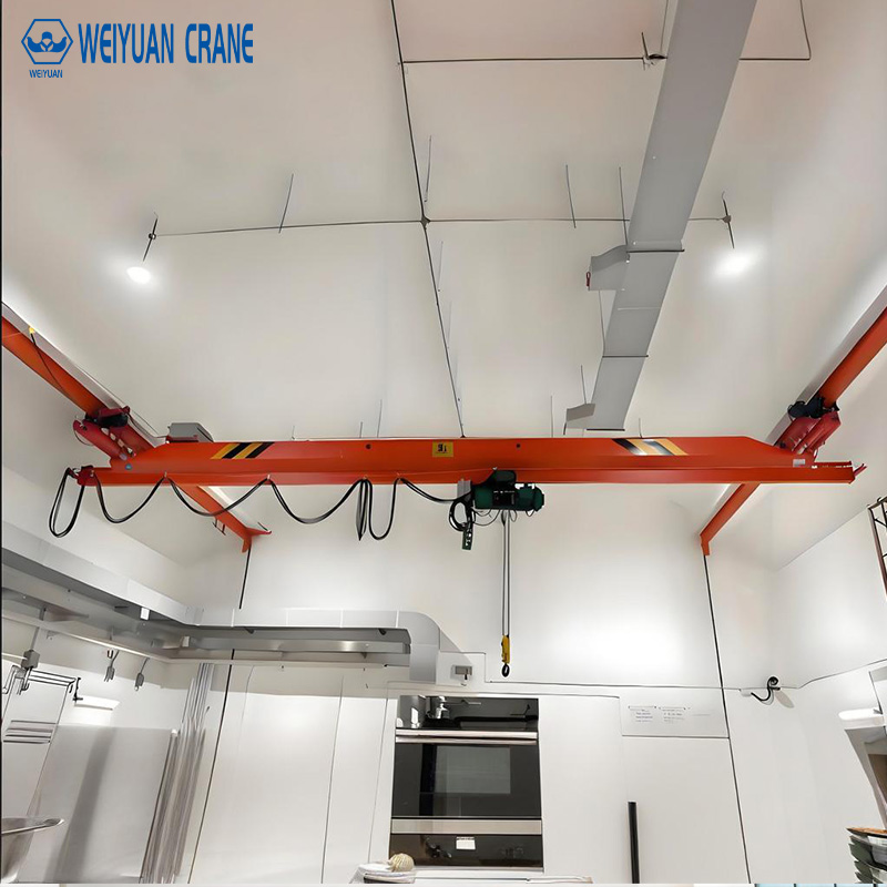
In an under-running (underhung) system, the crane’s wheels run on the bottom flange of the runway beam, so the crane hangs beneath the beam rather than riding on top of it.
- Capacity: generally lighter, commonly up to around 10 tonnes.
- Headroom: recovers valuable hook height, since the bridge tucks up close to the roof.
- Strengths: low headroom, the ability to run close to the building sides, and support for multiple cranes on one runway with track switches.
- Best for: light-to-moderate assembly, workshops, and low-headroom bays.
A key structural point: an under-running crane loads the bottom flange of the beam in local bending, so the beam flange must be verified for that concentrated wheel load, not just the beam’s overall capacity.
Single Girder vs Double Girder
The crane’s own configuration also shapes the runway. A single-girder crane is lighter and imposes lower wheel loads, so its runway beams and rails can often be lighter. A double-girder crane is heavier, carries more, and imposes higher wheel loads — demanding stronger runway beams, heavier rails, and more robust column connections. Confirm the crane configuration before designing the runway, because the wheel loads it delivers drive every downstream decision. For help settling the crane configuration itself, see our overhead crane buying guide.
Takeaway: Top-running suits heavy capacity and long spans; under-running saves headroom for lighter loads. A double-girder crane needs a stronger runway than a single-girder one — so fix the crane type first.
Runway Rail Selection
The rail is the surface the wheels run on, and matching it to the wheel load is central to even wear and long service life.
Why the Rail Matters
Each crane wheel presses a concentrated contact force onto the rail head, and the rail spreads that force into the beam below. Too light a rail for the wheel load and the head wears rapidly, mushrooms, and transmits a rough ride into the crane and the structure. The right rail carries the wheel load comfortably, wears slowly, and keeps the crane tracking true.
Types of Rail
Three rail options appear on overhead runways:
- Crane rail (A-series / heavy rail): purpose-made rail with a wide head and foot, designed for high wheel loads and heavy duty. The standard for medium and heavy top-running cranes.
- Flat-bottom (train) rail: ASCE or similar profiles, sometimes used for lighter cranes, though the profile is optimized for railway wheels rather than crane wheels.
- Square or rectangular bar: economical for the lightest, low-wheel-load cranes on short runs.
For under-running cranes, there is no separate rail — the crane wheels run directly on the beam’s bottom flange, so the beam itself must be a suitable rolled section with a flange rated for the wheel contact.
Matching Rail to Wheel Load and Duty
Rail size follows the crane’s maximum wheel load and duty class, both of which the crane supplier provides. A heavy, high-cycle crane needs a substantial crane rail with a wide head to spread contact stress and resist wear; a light, occasional-use crane can run on a lighter section. Under-specify and you get rapid head wear and a rough-running crane; over-specify and you pay for steel you never use. A higher duty class means more cycles, which pushes you toward a heavier, more wear-resistant rail even at the same capacity.
Takeaway: Match the rail to the maximum wheel load and duty class — crane rail for heavy duty, lighter sections for light duty — and always size it from the supplier’s real wheel-load figures.
Structural Load Requirements
A runway must carry three kinds of load, and a design that considers vertical weight alone is dangerously incomplete. The side and end forces of a moving crane are what crack connections and skew bridges over time.
Vertical Load
This is the obvious one: the crane’s dead weight plus the rated load plus all rigging, delivered through the wheels onto the runway beams. Vertical load, combined with an impact allowance for the dynamic effect of lifting and lowering, sizes the beam for bending and deflection. The beam must carry the peak wheel load at every point along its length, since the crane travels the full runway.
Lateral Load (Side Thrust)
As the crane accelerates and decelerates its trolley, and as the bridge travels with any slight skew, it pushes sideways on the rails — a horizontal force acting across the top of the runway. This side thrust is a defined percentage of the lifted load plus trolley weight, applied horizontally, and it is one of the most commonly under-designed forces in a runway.
Side thrust does two things: it tries to bend the beam sideways (so the beam needs lateral strength or a horizontal bracing system), and it pushes on the columns and their connections. A column verified for vertical load alone may fail under the repeated sideways push of a busy crane, so the columns must be checked for side thrust specifically.
Longitudinal Load
When the whole traveling crane starts and stops, it creates a force along the length of the runway — the longitudinal load — from acceleration and braking of the bridge mass. This force tries to push the rails and beams along their axis and rack the structure lengthwise. It sets the requirement for longitudinal bracing in the runway and for anchoring that holds the rail firmly against creep while still allowing thermal movement.
Takeaway: Design the runway for vertical load with impact, lateral side thrust, and longitudinal braking forces together. Verify the columns for side thrust, not just vertical weight — it is the force most often forgotten and most likely to crack connections.
Alignment Tolerances: CMAA and ASME B30.2
Alignment is where a runway succeeds or fails in service. Beams and rails sized correctly still run badly if they are not straight, level, and parallel within tolerance — and misalignment drives the wheel and flange wear that shortens a crane’s life.
The Governing Standards
- ASME B30.2 is the safety standard for overhead and gantry cranes, covering the runway as part of the crane system.
- CMAA Specification No. 70 defines crane classification, design, and the runway alignment criteria the installation must meet.
Build to both and you have a defensible, verifiable standard.
The Alignment Criteria
The critical runway tolerances, drawn from CMAA practice, are:
- Track gauge (span between rail centerlines): within ±3mm of nominal at any point along the runway.
- Elevation difference between the two rails at any cross-section: ±10mm maximum.
- Rail straightness (horizontal): within ±3mm in any 6-metre length, and within a defined total across the full runway.
- Rail elevation variation (vertical waviness): within ±3mm over the runway length.
- Rail joint step: no more than about 0.5mm vertical or horizontal step at any joint.
Confirm the exact figures against the crane manufacturer’s requirements and the CMAA edition you build to, since a heavier or faster crane may demand tighter tolerances.
Why Each Tolerance Matters
Each targets a specific failure mode. Gauge error forces the wheel flanges hard against the rail, wearing them and skewing the bridge. Elevation difference makes the crane run cross-level, loading one rail harder than the other. Straightness and waviness errors make the bridge weave and bounce as it travels, roughening the ride and fatiguing the structure. And a rail joint step becomes a hammer blow on every wheel pass, wearing the wheel tread and cracking the rail and beam over time.
These are acceptance criteria, not aspirations. Survey and confirm them before the crane enters service, and re-check them periodically — a detail that ties directly into the runway checks in our overhead crane maintenance and inspection guide, where uneven flange wear is the early warning that the runway has drifted out of tolerance.
Takeaway: Design and build to the CMAA gauge, elevation, straightness, waviness, and joint-step tolerances. Survey them at installation and re-check them, because a runway out of alignment quietly destroys wheels, flanges, and structure.
Rail Anchoring and Thermal Expansion
How the rail attaches to the runway beam decides whether it stays put, stays aligned, and survives temperature cycling over decades.
The Two Demands on Anchoring
Rail anchoring must do two things that pull against each other:
- Hold the rail firmly against vertical, lateral, and longitudinal movement, so it does not creep or shift under wheel and travel loads.
- Allow thermal expansion and contraction along the rail’s length, without building up compressive stress — a real factor in bays that heat and cool through daily and seasonal swings.
Anchoring Done Right
The correct method is a rail clip system that grips the rail foot against movement while letting it slide longitudinally as it expands. For it to work over the life of the crane:
- Set the clip spacing to the design interval, closer where duty and lateral loads are heavy.
- Torque the clips to specification — too loose and the rail creeps, too tight and it cannot move thermally.
- Use the correct clip type for the rail profile, and adjust for fine lateral alignment during installation.
Where rails meet end to end, the joint must be aligned flush to hold the joint-step tolerance, and gapped correctly to accommodate expansion.
Why Welding the Rail Solid Is Wrong
The most damaging anchoring mistake is welding the rail solid along its full length to the beam. It locks in the thermal expansion the rail must accommodate. Over a few seasons the compressive stress builds until the rail buckles into humps or lifts, leaving a wavy rail that is expensive to correct and destructive to wheels. Always clamp with clips; never weld a running crane rail solid.
Takeaway: Anchor with a clip system that grips the rail against movement while allowing thermal expansion. Set spacing and torque to spec, align joints flush, and never weld the rail solid.
End Stops and Buffers
At each end of the runway, the crane must stop safely at the limit of travel. End stops and buffers are the last line of defense against a moving crane running off its rails.
What They Do
- End stops are physical barriers fixed at each end of the runway that the crane cannot travel past — the hard limit of travel.
- Buffers are energy-absorbing devices on the crane or the end stop that cushion the impact, turning a potential crash into a controlled deceleration.
Both back up the crane’s electrical travel limit switches, which slow and stop the bridge before it reaches the buffers in normal operation. The buffers and stops are the mechanical safety net for when the limit switches or the operator fail.
Sizing and Placement
Buffers must be sized for the crane’s weight and travel speed, because the kinetic energy they absorb grows with both — and it grows with the square of the speed, so a fast crane demands far more capable buffers than its weight alone suggests. Common types include rubber, cellular polyurethane, and hydraulic units, chosen by the energy they must dissipate. Under-size a buffer and it bottoms out, transferring a hard shock into the crane and the end stop.
Place the end stops so both ends of the bridge reach their stops squarely at the same moment; a bridge that hits one stop before the other skews hard at impact, loading the structure unevenly. The end stops themselves must be anchored to carry the impact force into the runway beam.
Takeaway: End stops halt the crane and buffers absorb the impact, backing up the travel limit switches. Size buffers to the crane’s full weight and travel speed, and place stops for square, simultaneous contact on both rails.
Conductor Bar and Festoon Power Supply
Power must reach a crane that travels the full length of the runway, and how you route it affects both reliability and the nuisance faults that plague a poorly planned system. Two methods dominate.
Conductor Bar (Bus Bar)
A conductor bar system runs a fixed, enclosed electrical bar along the length of the runway, and a collector mounted on the moving crane slides along it, picking up power continuously.
- Strengths: compact, tidy, low-maintenance, and well suited to long runways and high travel speeds.
- Best for: most modern top-running cranes, long bays, and dusty or busy environments where a trailing cable would snag.
- Key detail: the bar must be aligned straight and level along the full travel, and expansion sections fitted on long runs, so the collector runs cleanly with no gaps or high spots.
Festoon Cable
A festoon system hangs a flat or round cable from carriers (trolleys) that slide along a track beside the runway, gathering and spreading like a curtain as the crane moves.
- Strengths: simple, economical, and able to carry both power and control or data cables together.
- Best for: shorter runways, lighter cranes, and installations where multiple conductors are needed.
- Key detail: route the cable to follow the full travel without dragging, stretching, or over-bending, and keep it within its minimum bending radius so it does not fatigue at the flex points.
Routing Both Correctly
Whichever you choose, plan the routing at design stage, not after the crane is up:
- Run the system clear of the crane’s travel path and any fixed obstruction across the full length.
- Confirm the collector or festoon track follows the runway alignment, so it does not bind at the extremes of travel.
- Size the conductors for the crane’s full-load and starting current, and confirm voltage drop stays within limits at the far end of a long runway.
- Bond the system to earth and match any enclosure to the bay’s IP rating for dust and moisture.
Poorly routed festoon cable and misaligned conductor bar are two of the most common sources of nuisance faults on a moving crane, so treat the power supply as part of the runway design.
Takeaway: Conductor bar suits long, fast, tidy installations; festoon suits shorter runs and multi-cable needs. Either way, route it clear of obstructions, follow the runway alignment, size the conductors for the load, and plan it at design stage.
Comparing the Runway Beam Options at a Glance
Use this table to narrow the configuration, then confirm the detail against your crane’s real loads and your building.
| Configuration | Typical capacity | Headroom use | Rail arrangement | Best for |
|---|---|---|---|---|
| Top-running, single girder | Light to moderate | More | Rail on top flange | Workshops, moderate loads, longer spans |
| Top-running, double girder | Moderate to heavy | More | Heavier rail on top flange | Heavy manufacturing, steel, foundries |
| Under-running (underhung) | Up to ~10 t | Low (saves height) | Wheels on bottom flange | Low-headroom bays, light assembly, multi-crane runs |
How to Read the Table
Start with capacity and headroom. Heavy loads and long spans point to a top-running configuration, single girder for lighter duty and double girder for heavy. Tight headroom with lighter loads points to under-running, which tucks the crane up near the roof and can run close to the building sides. Then confirm the choice against the wheel loads the crane delivers and what your columns can carry.
Takeaway: Capacity and headroom set the beam configuration; the crane’s wheel loads and your building structure confirm it.
A Practical Runway Design Framework
Here is how to reach a sound overhead crane runway design without guesswork. Work through the steps in order.
Step 1: Get the Crane Data First
Start with the crane’s maximum wheel loads, span, duty class, weight, travel speed, and impact allowance — all from the supplier. The runway cannot be designed until these are fixed, because they drive every decision downstream. If the crane configuration itself is not settled, resolve it first with our overhead crane buying guide.
Step 2: Verify the Building Structure
Confirm the columns, their foundations, and the roof structure can carry the runway loads. This is where an overhead runway differs most from a gantry runway — the building is the foundation, so the columns must be checked for vertical load, side thrust, and longitudinal force before anything is designed on top of them.
Step 3: Design the Beams and Select the Rail
Size the runway beams for vertical load with impact, lateral side thrust, and deflection limits, adding horizontal and longitudinal bracing as the loads require. Match the rail to the maximum wheel load and duty class, or verify the bottom flange for an under-running crane.
Step 4: Specify Alignment, Anchoring, and Stops
Set the CMAA and ASME B30.2 tolerances as acceptance criteria, specify a clip anchoring system that allows thermal movement, and size the end stops and buffers to the crane’s weight and travel speed.
Step 5: Plan the Power Supply
Choose conductor bar or festoon, route it clear of the travel path along the full runway, size the conductors for the load, and confirm the voltage drop at the far end.
Takeaway: Crane data, then building structure, then beams and rail, then alignment and anchoring, then power supply. Work through them in order and the design emerges from real numbers rather than assumptions.
Frequently Asked Questions
Q: What is an overhead crane runway?
An overhead crane runway is the pair of parallel elevated beams, each carrying a rail, that an overhead crane’s bridge travels along. It also includes the support columns and brackets, the rail anchoring, the end stops and buffers, and the power supply system. Unlike a gantry crane runway set at ground level, an overhead runway transfers every force — the crane’s weight, the rated load, and the side and end forces of travel — into the building structure. The beams carry the crane, the columns carry the beams, and the foundations carry the columns, so the building itself is effectively the crane’s foundation.
Q: What is the difference between a top-running and an under-running runway?
In a top-running system, the crane’s wheels run on a rail mounted on the top flange of the runway beam, with the bridge above the rails — the standard for medium and heavy cranes and long spans, at the cost of more headroom. In an under-running (underhung) system, the crane’s wheels run on the bottom flange of the beam, so the crane hangs beneath it, saving valuable hook height and allowing the crane to run close to the building sides. Under-running suits lighter loads (commonly up to around 10 tonnes) and low-headroom bays, and its beam bottom flange must be verified for the concentrated wheel load.
Q: How do I choose the right rail for an overhead crane runway?
Match the rail to the crane’s maximum wheel load and duty class, both provided by the crane supplier. Heavy, high-cycle top-running cranes need a purpose-made crane rail (A-series) with a wide head to spread the concentrated contact stress and resist wear. Lighter cranes on short runs can use a flat-bottom rail or bar stock. A higher duty class means more cycles, which pushes you toward a heavier, more wear-resistant rail even at the same capacity. Under-specifying causes rapid head wear and rough travel; over-specifying wastes money. For an under-running crane, the wheels run on the beam’s bottom flange, so no separate rail is used.
Q: What loads does an overhead crane runway have to carry?
Three kinds. Vertical load is the crane’s dead weight plus the rated load plus rigging, with an impact allowance for lifting, and it sizes the beam for bending and deflection. Lateral load, or side thrust, is a horizontal force across the top of the runway from trolley acceleration and bridge skew, and it must be carried by both the beam (in lateral bending or bracing) and the columns. Longitudinal load comes from the whole crane starting and stopping, pushing along the runway’s length and setting the need for longitudinal bracing and firm rail anchoring. Side thrust is the force most commonly under-designed, so verify the columns for it specifically.
Q: What alignment tolerances apply to an overhead crane runway?
Per CMAA and ASME B30.2 practice, the key tolerances are: track gauge within about ±3mm of nominal at any point, elevation difference between the two rails within about ±10mm at any cross-section, rail straightness within roughly ±3mm over a defined length, rail elevation waviness within about ±3mm over the runway, and rail joint steps no greater than about 0.5mm. Confirm the exact values against your crane manufacturer’s requirements and the CMAA edition you build to, since heavier or faster cranes may demand tighter limits. These are acceptance criteria — survey them at installation and re-check them periodically, because a runway drifting out of tolerance drives flange and wheel wear.
Q: Why can’t an overhead crane rail be welded solid to the beam?
Because the rail expands and contracts with temperature, and welding it solid along its full length leaves that movement nowhere to go. As the bay heats and cools, compressive stress builds in the locked rail until it buckles into humps or lifts off the beam, leaving a wavy, damaged rail that destroys wheel treads and is costly to correct. The right method is a rail clip system: the clips grip the rail foot firmly against vertical, lateral, and longitudinal movement while still allowing it to slide as it expands. Always clamp with clips, and never weld a running crane rail solid.
Q: How are end stops and buffers sized for an overhead crane?
Buffers are sized to the kinetic energy of the moving crane, which grows with its weight and with the square of its travel speed — so a fast crane needs far more capable buffers than its weight alone suggests. Common buffer types include rubber, cellular polyurethane, and hydraulic units, selected by the energy they must dissipate. Under-size a buffer and it bottoms out, transferring a hard shock into the crane and the end stop. Place the end stops so both ends of the bridge reach them squarely at the same moment, since a bridge that hits one stop first skews hard at impact. Buffers and stops back up the travel limit switches, not replace them.
Q: Should I use conductor bar or festoon for the crane power supply?
Choose a conductor bar (bus bar) system for most modern top-running cranes, long runways, and high travel speeds — it is compact, tidy, and low-maintenance, with a collector on the crane sliding along a fixed enclosed bar. Choose a festoon cable system for shorter runways, lighter cranes, or where you need to carry power plus control or data cables together, since it hangs cable from sliding carriers. Either way, route the system clear of the travel path, align it to the runway so it does not bind at the extremes, size the conductors for the full-load and starting current, and confirm the voltage drop at the far end of a long runway.
Q: Does the runway need to be designed together with the crane?
Yes — the crane and its runway are a single system. The crane’s wheel loads, span, duty class, weight, travel speed, and impact allowance all drive the beam sizing, rail selection, alignment tolerances, anchoring, buffer sizing, and power supply. Designing the runway in isolation, or ordering the crane before verifying that the building columns can carry the vertical, lateral, and longitudinal loads, is a common and costly mistake. Confirm the crane specification first, verify the building structure, and coordinate the runway design as one package from the start.