


Electric Hoist Installation Guide: Mounting, Electrical Connection, and Commissioning Best Practices
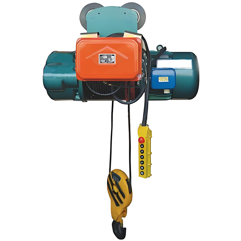
Introduction
An electric hoist can be perfectly specified and still fail early — because the failure was built in during installation, not selection. A hook that hangs a few degrees off vertical. A phase rotation nobody checked, so “up” lowers the load. A brake commissioned in a rush before anyone tested it under weight. None of these show up on the day the hoist arrives. They surface weeks later as uneven rope wear, a load that drifts, or a two-block event that snaps the chain.
Installation is where the money you spent on the right hoist either pays off or quietly leaks away. A well-chosen unit installed poorly delivers a fraction of its rated life and becomes a recurring maintenance cost — the exact opposite of the equipment uptime you bought it for. Get the installation right and the hoist lifts smoothly, holds the load safely, and runs for years with little more than routine care.
This guide walks through the complete installation and commissioning process from a plant engineer’s and facility manager’s point of view. This is article 3 of 3 in the Weiyuan Crane electric hoist series. Where article 1 covered electric hoist types and applications and article 2 covered the electric hoist buying guide, this one covers how to install and commission the hoist so it performs for its full service life.
Here is what you will learn:
- How to prepare the site, verify the structure, and confirm the power supply
- The mounting sequence for fixed and trolley-mounted hoists
- How to connect the electrics, commission every motion, and load test to standard
- The alignment tolerances and common mistakes that cause long-term trouble
Part 1: Pre-Installation Checks
Everything that goes wrong later is cheaper to fix before the hoist is mounted. Pre-installation is where you confirm the structure, the power, and the delivered parts are actually ready — not assumed to be.
Verify the Supporting Structure
An electric hoist concentrates its full load — the rated capacity plus its own weight plus dynamic lifting forces — onto whatever it hangs from. That support must be confirmed before anything is lifted:
- The beam or crane must be rated for the hoist load. Confirm the runway beam, jib boom, or monorail carries the hoist’s dead weight, the rated load, and the impact of lifting, at the mounting position.
- Check the flange dimensions. For a trolley-mounted hoist, confirm the beam flange width and thickness match the trolley’s adjustment range, so the trolley wheels seat correctly on the flange.
- Confirm the fixing points. For a fixed hoist, verify the mounting bracket, lug, or hook anchor is sound and rated for the load.
A beam sized only for its own weight, or a flange the trolley cannot grip, is a hazard that surfaces the first time a load hangs from it.
Confirm the Power Supply
Match the incoming supply to the hoist nameplate before installation day, not during it:
- Voltage and phase must match — single-phase or three-phase, at the correct voltage.
- Frequency must match, since it sets motor speed.
- Full-load current and protection must be sized for the hoist’s running and starting current.
A three-phase hoist ordered for a single-phase site — or the reverse — stalls the whole installation, so confirm this early against the specification you developed in the electric hoist buying guide.
Inspect the Delivered Components
When the hoist arrives, inspect it before installation, not after. Check the hoist body, trolley, hook and latch, wire rope or load chain, pendant or remote, and the power supply components against the packing list and drawings. Look for transit damage, confirm the rope seats correctly on the drum or the chain feeds cleanly over the sprocket, and verify every bolt and fitting is present. A missing bracket discovered mid-installation stops the whole job.
Takeaway: Pre-installation is verification, not paperwork. Confirm the structure carries the load, the power matches the nameplate, and the delivered parts are complete and undamaged before mounting anything.
Part 2: Mounting the Hoist
With the structure verified and the power confirmed, the hoist goes up. The mounting method depends on whether the hoist is fixed for straight lifting or trolley-mounted to traverse a beam. Each follows a clear sequence, and both share one rule: confirm the mount is sound before any load hangs from it.
Fixed Beam Mount
A fixed hoist lifts straight up and down from one point, without traversing.
- Confirm the anchor point — the bracket, lug, or beam clamp — is rated for the load and securely fixed to the verified structure.
- Mount the hoist body to the anchor, torquing every fixing to the manufacturer’s specification with a calibrated wrench.
- Confirm the hoist hangs plumb so the hook centers directly below the drum or lift wheel and the load lifts vertically.
- Check the rope or chain feed is clear of any obstruction across the full lift height.
Trolley-Mounted Installation
Most hoists mount on a trolley that traverses a beam or crane bridge. There are three trolley types, and the installation sequence is similar for each.
- Set the trolley onto the beam flange. Fit the side plates around the flange and adjust the wheel spacing to the flange width, leaving the correct clearance so the wheels roll freely without excessive side play.
- Confirm the adjustment. Too tight and the trolley binds; too loose and it rocks and wears the flange edges. Set it to the specified clearance and lock the adjustment.
- Fit the end stops on the beam so the trolley cannot run off either end.
- Mount the hoist to the trolley and torque the connection to specification.
The three trolley types differ in how they travel:
- Plain (push) trolley: moved by hand or by pushing the load. Confirm it rolls freely along the full beam length with a light push.
- Geared trolley: moved by pulling a hand chain. Confirm the hand chain drives the trolley smoothly in both directions without slipping.
- Motorized trolley: powered traverse. Confirm the travel motor and its drive are wired and secured — the travel motion is then commissioned with the rest of the electrics.
For every type, confirm the trolley traverses the full beam freely and the hoist hangs plumb before connecting power.
Takeaway: Mount the hoist to a verified anchor or a correctly adjusted trolley, torque every connection to specification, and confirm the hoist hangs plumb and travels freely before any load or power goes near it.
Part 3: Electrical Connection
A mechanically mounted hoist does nothing until the electrical system is connected correctly — and nothing safely until it is proven. This phase powers the hoist and prepares it for commissioning.
Match and Connect the Supply
Connect the incoming supply to the hoist’s feed point, confirming once more that the voltage, phase, and frequency match the nameplate exactly. Size the incoming cable and its protection for the hoist’s full-load and starting current, and confirm the voltage drop stays within limits at the hoist under load, especially on a long trolley run.
Wiring and Cable Management
Route the power to the hoist and, on a trolley-mounted unit, to the traveling hoist through a festoon cable system or a conductor bar:
- Festoon: the cable hangs from carriers that slide along a track beside the beam, gathering and spreading as the trolley moves. Route it to follow the full travel without dragging, stretching, or over-bending, and keep the cable within its minimum bending radius.
- Conductor bar: a collector on the trolley runs along a fixed enclosed bar. Confirm the bar is aligned along the whole travel so the collector runs cleanly with no gaps.
Poorly routed festoon cable is one of the most common sources of nuisance faults on a moving hoist, so take the time to hang it correctly.
VFD Setup
Where a variable frequency drive is fitted, confirm its settings before commissioning:
- Acceleration and deceleration ramps set for smooth, jolt-free starts and stops.
- Speed settings — including slow-speed positioning — matched to the application.
- Motor parameters entered correctly for the specific hoist motor.
A VFD delivers its benefits — reduced wear, accurate positioning, lower starting current — only when it is configured for the hoist and the duty, so do not skip this step.
Earthing and Bonding
Bond the hoist body, the trolley, the beam or crane structure, and any control enclosure to a common earth per the applicable electrical code, and verify continuity across every point. Proper earthing protects against shock if a fault energizes the structure and keeps stray currents from disturbing the controls — skip it and you invite both a hazard and maddening intermittent faults.
Confirm the IP Enclosure
Confirm the hoist and any panel enclosure match the site’s IP rating — IP54 for clean indoor bays, IP55 or IP65 for dusty or damp conditions, and higher for outdoor or harsh sites. Check that seals are intact and all cable entries are sealed. An under-rated or unsealed enclosure lets dust and moisture reach the electrics, causing the corrosion and faults that quietly erode uptime.
Takeaway: Match the supply to the nameplate, route the cabling to follow the trolley without snagging, configure the VFD for the duty, bond the whole system to earth, and confirm the enclosure is sealed to its rating before energizing.
Part 4: Commissioning Steps
Commissioning is where the hoist becomes safe to use, not just able to move. Work through the sequence in order — each step confirms the hoist responds correctly and stops safely before it ever carries a full load.
Step 1: Confirm Phase Rotation and Motion Direction
Power up and check every motion runs in the correct direction against the pendant or remote labels. On a three-phase supply, a reversed phase makes “up” lower the load — a serious hazard, and one of the most common commissioning faults. Many hoists include a phase-reversal relay that blocks operation if the rotation is wrong. Test hoist up and down, and trolley travel where powered, and correct any reversed motion before going further.
Step 2: Test the Limit Switches
- Upper limit: run the hook up slowly and confirm it stops before two-blocking — before the hook block reaches the drum or lift wheel. Test the backup final limit where fitted. Never bypass this switch; it prevents the two-block event that can snap the rope or chain and drop the load.
- Lower limit: run the hook to its lowest point and confirm it stops with the specified number of rope wraps still on the drum, or with chain to spare, so the anchorage is never fully unwound.
Step 3: Test the Brake Under Load
Raise a test load clear of the ground, hold it stationary, and watch for any downward drift. A brake that lets the load creep is worn, misadjusted, or contaminated with oil, and it must be resolved before the hoist enters service. The brake is what holds every load whenever the motor stops, so this test is never skipped.
Step 4: Verify the Overload Device
Where an overload limiter is fitted, apply a load above its set threshold — typically 100 to 110% of rated capacity — and confirm it cuts the lift command and prevents the hoist from raising the load further. This device is a critical backstop against overload; verify it works rather than assuming it does.
Step 5: Confirm Controls and Emergency Stop
Confirm every pendant or remote button responds correctly and matches its label. Test the emergency stop and confirm it drops all motion instantly and requires a deliberate reset before the hoist will run again. Confirm any warning devices — horns, beacons — work. Log every check with a result and a date.
Takeaway: Commission in sequence — phase rotation, limit switches, brake under load, overload device, then controls and emergency stop. Prove every motion and safety device before the hoist carries a full working load.
Part 5: Load Testing to ASME B30.2 and Relevant Standards
Load testing is the final proof that the hoist performs as designed and is safe to release into service. ASME B30.2 governs overhead and gantry cranes and their hoists, and ASME B30.16 covers overhead hoists specifically — both set the same core framework for testing before first use.
Step 1: No-Load Functional Test
Run every motion through its full range unloaded first — hoist up and down, and trolley travel where powered. Confirm smooth operation, correct limit stops at both ends, the brake holding at every stop, and the trolley tracking freely without binding. Resolve any roughness here, before adding weight.
Step 2: Rated Load Test
Lift the rated capacity and confirm the hoist raises and lowers it smoothly, with the brake holding the load without drift. Traverse the load where the hoist is trolley-mounted, and confirm the travel motion handles it. Watch and listen for unusual noise, vibration, or movement at the mount.
Step 3: 125% Overload Test
Before first use, a new hoist is tested with an overload. The test load must not exceed 125% of rated capacity unless the manufacturer specifies otherwise. Lift the test load, confirm the hoisting mechanism, brake, and structure perform without distress, and inspect the mount, trolley, and supporting beam for any sign of deflection, movement, or distress under the overload. This is where a marginal mount or an under-rated beam reveals itself.
The same overload test applies after any repair or modification affecting a load-bearing component or safety device.
Step 4: Record and File the Result
Document the test load, the date, and the outcome, signed by the qualified person who performed the test. This certified record proves the hoist was verified at capacity, satisfies your compliance obligations, and becomes the baseline your maintenance program measures against. File it with the hoist’s inspection and maintenance history.
Takeaway: Test in stages — no-load, rated load, then the 125% overload — verify both the hoist and travel motions, inspect the mount under overload, and keep a dated, signed certificate as proof and as your maintenance baseline.
Part 6: Alignment and Installation Tolerances
A hoist runs well and wears evenly only when it hangs true, the rope or chain seats correctly, and the brake is set right. Confirm these after installation and before load testing.
Hook Vertical Alignment
The hook must hang plumb, directly below the drum or lift wheel, so the load lifts straight up. A hoist mounted off-plumb pulls the load sideways as it lifts, dragging the rope against the drum flange or the chain against the guide, wearing both prematurely. Check the hook centers under the lifting point and correct the mounting if it does not.
Rope or Chain Seating
- Wire rope: confirm the rope winds onto the drum in even, adjacent turns without crossing or gapping, and that it seats cleanly in the drum grooves. A rope that spools unevenly wears at the crossover points and can jump the groove.
- Load chain: confirm the chain feeds smoothly over the lift wheel, seating fully in each pocket without twist. A twisted or poorly seated chain wears the sprocket and can jam or jump.
Check the rope or chain runs true through its full lift height, with the slack chain gathering cleanly in its container where fitted.
Brake Adjustment
Confirm the brake is set to the manufacturer’s specification and holds the rated load without drift, as proven in commissioning. A correctly adjusted brake engages the moment the motor stops and releases cleanly when it starts. Confirm the setting rather than assuming the factory setting survived shipping.
Fixing Torque
Confirm every mounting and trolley bolt is torqued to specification and marked, so nothing works loose under cyclic load.
Document every reading in an as-installed report and retain it as your compliance record and the baseline for future checks.
Takeaway: Confirm the hook hangs plumb, the rope or chain seats cleanly, the brake holds without drift, and every fixing is torqued before load testing. A hoist that hangs true wears evenly and lasts its full life.
Part 7: Common Installation Mistakes to Avoid
Most electric hoists that give trouble were let down by a handful of avoidable errors. Knowing them upfront is the cheapest protection you can buy — and the surest way to keep the equipment uptime you bought the hoist for.
Mistake 1: Mounting to an Unverified Structure
The hoist is hung from a beam, boom, or bracket nobody confirmed for the load. The support flexes, cracks, or fails under working load.
Prevention: Verify the beam, flange, or anchor for the hoist dead weight, rated load, and lifting impact before mounting anything.
Mistake 2: Skipping the Phase Rotation Check
The hoist is used because it moves, before phase rotation is confirmed. A reversed phase makes “up” lower the load — and the operator discovers it the hard way.
Prevention: Confirm phase rotation and every motion direction against the controls during commissioning, before any load.
Mistake 3: Not Testing the Upper Limit
The upper limit switch is assumed to work and never tested. The first time the operator runs the hook too high, it two-blocks, snapping the rope or chain and dropping the load.
Prevention: Test the upper limit — and any backup final limit — slowly during commissioning, and never bypass it.
Mistake 4: Releasing the Hoist Without a Brake Test
The hoist goes into service before the brake is proven under load. A brake that drifts lets the load creep down, unnoticed until it matters.
Prevention: Test the brake under a held load for drift during commissioning, and resolve any creep before release.
Mistake 5: A Hoist That Hangs Off-Plumb
The hoist is mounted without confirming the hook centers below the lifting point. The load pulls sideways on every lift, wearing the rope, drum, or chain from the first shift.
Prevention: Confirm the hook hangs plumb and correct the mounting before load testing.
Mistake 6: Poorly Routed Festoon or Trolley Cable
The festoon cable is hung with too much or too little slack, so it drags, snags, or over-bends at the ends of travel, causing nuisance faults and early cable failure.
Prevention: Route the festoon or conductor bar to follow the full travel cleanly, within the cable’s bending radius, with no dragging or snagging.
Mistake 7: Under-Rated or Unsealed Enclosure
A standard-rated hoist is installed in a dusty or damp area, or the enclosure seals are left unchecked. Dust and moisture reach the electrics and corrode them.
Prevention: Confirm the IP rating matches the site and that every seal and cable entry is intact before energizing.
Mistake 8: Accepting Handover Without Documentation
The hoist is put to work with no commissioning record or load test certificate. When a problem appears later, there is no baseline to diagnose against and no proof of compliance.
Prevention: Insist on a complete, signed handover pack — commissioning log, alignment record, and load test certificate — before accepting the hoist.
Takeaway: Almost every long-term hoist problem traces back to an unverified mount, an untested safety device, an off-plumb hoist, or a missing record. Close those gaps and you close most of your future trouble.
Frequently Asked Questions
Q: How do I know if my beam can support an electric hoist?
The beam must be rated for the hoist’s own dead weight, the rated load, and the dynamic impact of lifting, all at the mounting position — not just a static load. For a trolley-mounted hoist, the beam flange width and thickness must also match the trolley’s adjustment range so the wheels seat correctly. Have the runway beam, jib boom, or monorail verified by a structural engineer for these combined loads before installation. A beam designed only for its own weight may not accept a hoist without reinforcement, so confirm this during pre-installation, not after.
Q: What is the most common electrical mistake when installing an electric hoist?
Reversed phase rotation on a three-phase hoist, which makes the “up” button lower the load and the “down” button raise it — a serious hazard. It happens because the incoming phases can be connected in any order, and the direction is only confirmed by testing. Many hoists include a phase-reversal relay that blocks operation when rotation is wrong, but the direction of every motion must still be checked against the pendant labels during commissioning, before any load is lifted. Correcting it is simple: swap two of the three supply phases.
Q: How do I test the brake on a newly installed electric hoist?
Raise a test load clear of the ground, hold it stationary with the controls released, and watch for any downward drift. A correctly adjusted brake engages the instant the motor stops and holds the load with no creep. If the load drifts down, the brake is worn, misadjusted, or contaminated with oil or grease, and it must be corrected before the hoist enters service. Confirm the brake holding at the rated load and again during the load test, since the brake is what secures every load whenever the motor is not driving.
Q: What is the load test requirement for a new electric hoist?
A new hoist must be tested before its first use, and again after any repair or modification affecting a load-bearing component or safety device. Per ASME B30.2 and B30.16 practice, the test load must not exceed 125% of the rated capacity unless the manufacturer specifies otherwise. Run a no-load functional test first, then a rated load test confirming the brake holds without drift, then the 125% overload test while inspecting the mount and beam for any distress. Keep a dated, signed certificate of the result as proof of compliance and as your maintenance baseline.
Q: Why must the hook hang vertically below the hoist?
Because the hoist is designed to lift straight up, and a hook that hangs off-plumb pulls the load sideways as it rises. That side pull drags the wire rope against the drum flange or the load chain against its guide, wearing both far faster than normal and, in severe cases, letting the rope jump the drum groove or the chain jam the sprocket. Confirming the hook centers directly below the drum or lift wheel is a quick check during installation that protects the most expensive wear parts and keeps the hoist tracking true for its full life.
Q: How is the trolley clearance set on a beam-mounted hoist?
The trolley side plates fit around the beam flange, and the wheel spacing is adjusted to the flange width to leave the correct running clearance. Set it too tight and the trolley binds and labors along the beam; set it too loose and it rocks side to side, wearing the flange edges and running roughly. Adjust the wheels to the manufacturer’s specified clearance for the measured flange width, lock the adjustment, and confirm the trolley rolls freely along the full beam length. Fit end stops at both ends so the trolley cannot run off.
Q: What safety devices must be tested when commissioning an electric hoist?
At minimum: confirm phase rotation so every motion runs the correct direction, test the upper limit switch (and any backup final limit) to prevent two-blocking, test the lower limit to keep rope on the drum, test the brake under a held load for drift, and verify the overload device cuts the lift at its threshold. Also confirm the pendant or remote responds correctly and the emergency stop drops all motion instantly and requires a deliberate reset. Log every check with a result and date, and hand over no hoist until each device is proven to work.
Q: What should be included in the installation handover package?
A complete handover pack includes the as-installed alignment record (hook plumb, rope or chain seating, brake setting), the fixing torque record, the electrical commissioning log (phase rotation, limit switches, brake, overload device, and earthing continuity), the signed load test certificate, confirmation of the correct IP enclosure, and the documentation pack — operating manual, maintenance schedule, and spare parts list. These documents prove the installation was done correctly, satisfy compliance requirements, and form the baseline your maintenance program measures against for the life of the hoist.