


Gantry Crane Drive Systems & VFD Control
Introduction
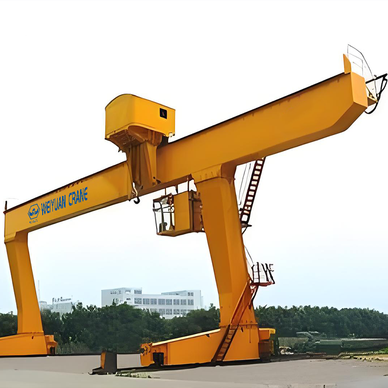
A steel service center I worked with had a 25-tonne double-girder gantry that looked perfect on paper. The right capacity, the right span, the working envelope calculated properly — the geometry work from article 1 in this series done well. What let it down was the drive system, and specifically the decision to save money on it.
The crane ran single-speed contactor drives on both bridge and trolley — full speed or nothing, on both motions. Every time an operator tapped the bridge control, the crane lurched from a dead stop to 40 metres a minute instantly, the load swung like a pendulum, and the operator spent the next fifteen seconds waiting for it to settle before he could place it. Spotting a coil onto a narrow saddle became a fight: bump forward, overshoot, bump back, overshoot again, chase it in. A lift that should have taken ninety seconds took four minutes, and it hammered the crane doing it — the jolt starts drove shock loads into the wheels and rails on every single move.
Within three years the wheel flanges were wedge-worn, the rail heads were spalling, and the travel motors were tripping on overcurrent from the constant hard starts. The service center replaced the whole drive package with VFDs — the system they should have specified at the start — and the difference was immediate: smooth acceleration, no load swing, coils spotted first time, and the shock loading that was eating the runway simply gone. The crane was right. The drive system was the cheapest line on the original quote, and it cost them the most.
That’s the pattern with gantry drive systems. The structure gets the attention because it’s the visible, expensive steel. The drive — the motors, the controls, the way the crane accelerates and stops — gets specified last and cut first, and it decides whether the crane places loads precisely and lasts its full life, or fights the operator and grinds itself apart.
This is article 2 of our three-part gantry crane series, following article 1 on span, hook height, and the working envelope. Here we cover the systems that move the hook within that envelope: travel speeds and why bridge and trolley must be matched, the three drive types and how they differ structurally and operationally, how VFD control kills the jolt that wrecks runways, how fine-speed and inching enable precise spotting, drive sizing against duty class, encoder feedback and sway management, and the limit and anti-collision integration that keeps it all safe. Article 3 will close the series on power delivery and electrification across the span.
What you’ll take away:
- Why bridge travel and trolley travel speeds must be selected together, not in isolation
- The structural and operational differences between single-speed, dual-speed, and VFD drives
- How VFD eliminates jolt starts and stops, cuts dynamic wheel loads, and extends wheel and rail life
- How fine-speed and inching control turn a spotting fight into a first-time placement
- How to size the drive — motor rating and duty cycle — against CMAA A–F / FEM M3–M8
- What encoder feedback and anti-sway actually do
- How limit switches and anti-collision integrate with the drive
- A 2026 cost reference for drive and control upgrades
Part 1: Travel Speed Selection — Bridge vs Trolley, and the Mismatch Trap
A gantry crane has three motions, and two of them are travel: the bridge runs the whole crane along the runway (long travel), and the trolley runs the hoist across the bridge (cross travel). Each has its own speed, and the first mistake buyers make is picking those speeds in isolation — or worse, letting the supplier default them — without thinking about how the two work together and how far the load actually has to move.
Why Bridge and Trolley Speeds Differ
Bridge and trolley don’t do the same job, so they rarely want the same speed:
- Bridge (long travel) covers the long distances — the full length of the runway, often tens of metres. It benefits from a higher top speed so the crane doesn’t crawl the length of the yard on every cycle.
- Trolley (cross travel) covers the shorter span width and does most of the fine positioning across the bridge. It usually runs slower than the bridge, because precision matters more than distance here.
Typical ranges give a feel for it: bridge travel commonly runs 20 to 40 metres per minute on a production gantry (faster on long RMG runs), while trolley travel commonly runs 10 to 20 metres per minute. The exact figures follow the travel distance and the duty — but the principle holds: size the speed to the job the motion does, not to a single number applied to both.
The Mismatch Trap
Here’s the error the steel service center lived: speeds chosen without matching them to each other, or to the operator’s ability to control the load. Two failure modes show up:
- Too fast for the distance and control. A short trolley travel run at high speed means the operator is decelerating almost as soon as he’s accelerated — the crane never settles, the load swings, and precise placement is impossible. Speed you can’t use is speed that hurts you.
- Speed steps too coarse. On a single-speed drive, the only choice is full speed or stop. There’s no slow approach, so every placement is a series of bumps and overshoots. The mismatch isn’t between bridge and trolley here — it’s between the crane’s one speed and the fine control the job needs.
   SINGLE-SPEED vs CONTROLLED APPROACH

   SINGLE SPEED:  stop ──[FULL]──► overshoot ◄──[FULL]── bump back ──►
                  (chase the target, load swinging)

   CONTROLLED:    stop ──[fast]──► [slow] ─► [inch] ─► on target, settled
                  (one smooth approach)
Match the Speeds to the Work
The disciplined approach: define how the crane is actually used, then set the speeds to serve it.
- Bridge speed to the runway length and cycle time you need — fast enough to move efficiently, no faster than the operator can control on approach.
- Trolley speed to the placement precision the work demands — slower, because this motion does the spotting.
- Both with a controlled slow-speed range for the final approach, which is exactly what dual-speed and VFD deliver (Part 2).
Mini-takeaway: bridge and trolley are different jobs and want different speeds — size each to its distance and its role, and make sure both have a controlled slow range for the final approach. A single fast speed on either motion is a spotting fight and a load swing waiting to happen.
Part 2: Single-Speed vs Dual-Speed vs VFD — The Drive That Shapes Everything
Once you know the speeds you want, the next decision is how the drive delivers them — and this is the choice that most shapes how the crane behaves, how precisely it places loads, and how long the runway lasts. Three drive types dominate gantry travel, and they differ structurally, not just in price.
Single-Speed (Direct Contactor) Drive
The motor is switched straight onto full supply voltage by a contactor. It has one speed: full. Starting is a hard, direct-on-line jolt; stopping is an abrupt brake application.
Where it fits: the lightest, least frequent, least precise duty — a crane that moves occasionally and doesn’t need to spot loads finely. It’s the cheapest drive and the crudest.
The cost you don’t see on the quote: every start slams the crane from zero to full speed, and every stop slams it back — swinging the load and driving shock into the wheels and rails. This is the drive the steel service center regretted.
Dual-Speed (Two-Speed Motor) Drive
A two-speed motor (or two windings) gives a fast speed for travel and a slow speed for approach. The operator moves fast across the distance, then shifts to slow to spot the load.
Where it fits: moderate-duty cranes where some spotting precision is needed but full VFD isn’t justified. Dual-speed is a real improvement over single-speed — the slow speed makes controlled placement possible.
The limits: the shift between fast and slow is still a step, not a smooth ramp, so there’s a jolt at each speed change. Two fixed speeds are better than one, but they’re still fixed — you get the slow speed the motor was built for, not the speed the job wants.
VFD (Variable Frequency Drive)
A variable frequency drive controls the motor by varying the frequency and voltage supplied to it, giving stepless, fully adjustable speed from a crawl to full — with smooth, ramped acceleration and deceleration at every transition.
Where it fits: any duty where precision, smoothness, or runway life matters — which is most production gantries and all heavy or high-cycle ones. VFD is the modern default for a reason.
What it delivers: smooth ramps that eliminate the jolt (Part 3), an infinitely adjustable speed range that lets the operator dial in exactly the approach speed the load needs (Part 4), and dramatically reduced shock loading on the whole structure.
Side-by-Side
| Factor | Single-speed | Dual-speed | VFD |
|---|---|---|---|
| Speed control | One speed (full) | Two fixed speeds | Stepless, fully adjustable |
| Start / stop | Hard jolt | Step at each change | Smooth ramp |
| Spotting precision | Poor | Moderate | Excellent |
| Shock on wheels/rails | High | Moderate | Low |
| Load swing | Severe | Reduced | Minimal |
| Relative cost | Lowest | Moderate | Higher upfront |
| Best duty | Light, occasional | Moderate | Moderate to severe, precise |
Mini-takeaway: the drive type is a behavior decision, not just a price one. Single-speed jolts and swings; dual-speed adds a usable slow speed but still steps; VFD ramps smoothly through a stepless range. For any crane that places loads precisely or works hard, VFD is the drive that protects both the operator’s cycle time and the runway’s life.
Part 3: How VFD Kills the Jolt — And Why Your Runway Lasts Longer
The single biggest mechanical benefit of a VFD isn’t speed control for its own sake — it’s what smooth acceleration does to the forces the crane throws into its own structure. To see why, you have to look at what a jolt start actually does to the wheels and rails, and why the drive that eliminates it pays for itself in wheel and rail life.
What a Jolt Start Does
When a single-speed drive slams the motor to full speed instantly, the crane doesn’t just move — it lurches. That sudden acceleration creates a dynamic force on top of the static wheel load, and it hits everything at once:
- The wheels take an impact load far above their static share, on every start and every stop.
- The rails take the same impact through the wheel contact, concentrating shock at the rail head.
- The load swings, because the hook and its mass can’t accelerate instantly with the crane.
   JOLT START (single-speed)          RAMPED START (VFD)

   speed                              speed
     │    ┌──────────                   │        ╱────────
     │    │                             │      ╱
     │    │  ← instant jump             │    ╱  ← smooth ramp
     │    │     (shock load)            │  ╱     (no shock)
     └────┴──────────► time             └╱──────────► time

   Dynamic force spikes on every       Force stays close to static
   start and stop                      through the acceleration
The Dynamic Load Connection
Crane structures are designed with an impact factor added to the static load — commonly 15 to 25% for the lifting motion. But hard travel starts and stops add their own dynamic component on top, and a jolting drive pushes the real peak forces toward and past the top of that design allowance on every cycle. Over tens of thousands of cycles a year, that repeated shock is exactly what fatigues wheels, spalls rail heads, and loosens connections — the wear failures that plague a hard-driven runway.
A VFD ramps the speed up and down over a set acceleration time, so the crane’s momentum builds and bleeds off gradually. The dynamic force stays close to the static load throughout, and the shock component nearly disappears.
Why This Extends Wheel and Rail Life
Take it out of the abstract. A gantry that jolts on every move drives peak wheel loads well above the smooth-running case, tens of thousands of times a year. Those peaks are what:
- Wear the wheel treads and flanges faster
- Spall and crack the rail heads under repeated impact
- Fatigue the wheel bearings and the travel gearboxes
- Feed cyclic stress into the legs and connections
Smooth VFD ramps cut those peaks down to near the static load. The wheels roll instead of pound, the rails see steady contact instead of hammer blows, and the drivetrain runs without the repeated shock. The result is measurably longer wheel and rail life, fewer travel-motor faults, and less fatigue in the structure — the exact reversal of the steel service center’s spiral.
Mini-takeaway: the jolt from a hard drive is a shock load delivered to your wheels and rails on every start and stop, and it’s what wears them out early. VFD ramping keeps the dynamic force near the static load, so the runway sees rolling contact instead of hammer blows — which is why the drive that costs more upfront often costs less across the crane’s life.
Part 4: Spotting Accuracy — How VFD Fine-Speed and Inching Place the Load First Time
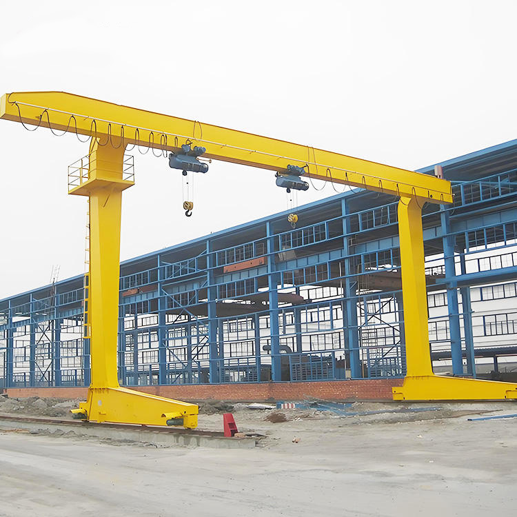
Smoothness protects the structure; fine control protects the operator’s time and the load. Spotting accuracy — the ability to place a load exactly where it needs to go, first attempt — is where a VFD earns its keep every single shift, and where a single-speed drive costs you on every lift. This is the difference between the steel service center’s four-minute coil fight and the ninety-second placement they got afterward.
Why Single-Speed Can’t Spot
To place a load precisely, the operator needs to creep the crane the last few centimetres and stop it exactly on target. A single-speed drive can’t creep — its only speed is full — so the operator is stuck bumping the control: a quick tap sends the crane lurching, it overshoots, he taps the other way, it overshoots again. The load swings through all of it. Precision is a matter of luck and patience, and both run out fast.
Fine-Speed Control
A VFD gives the operator a fine-speed range — a slow, stepless crawl he dials in for the final approach. Instead of full-speed bumps, he brings the crane in at a controlled creep, eases off as it reaches the mark, and sets the load down on target. The stepless range means he picks exactly the speed the placement needs, from a slow walk down to a crawl.
   SPOTTING A LOAD ONTO A NARROW SADDLE

   SINGLE-SPEED:  ▓▓▓▓►│    overshoot
                  │◄▓▓▓▓    overshoot back
                  ▓▓►│      overshoot again
                     ×      (eventually, roughly, on target)

   VFD FINE-SPEED: ──fast──►[slow]─►[crawl]─► ● on target, first time
Inching / Micro-Speed
For the tightest placements, a VFD offers inching (micro-speed) — the ability to move the crane a tiny, controlled increment at a very low speed, so the operator can nudge the load millimetres at a time. This is what lets a crane seat a coil on a narrow saddle, align a die to a press, or set a mold precisely on its bed — placements a bumping single-speed crane simply can’t achieve cleanly.
The Cycle-Time and Safety Payoff
Precise spotting isn’t just about the load. It buys back real time and cuts risk:
- Cycle time: a first-time placement is dramatically faster than a bump-and-chase — the steel service center’s coil lift went from four minutes to ninety seconds purely on control.
- Safety: a load that isn’t swinging and overshooting is a load under control, near people and equipment. Smooth spotting removes the swing that a bumping drive creates.
- Operator strain: the operator stops fighting the crane, which matters across a full shift at a busy station.
Mini-takeaway: spotting accuracy is where VFD pays back daily. Fine-speed gives a controlled creep for the approach, inching gives millimetre nudges for the tightest placements, and together they turn a bump-and-chase fight into a first-time set — faster, safer, and far less tiring than a single-speed drive can ever be.
Part 5: Drive System Sizing — Motor Rating and Duty Cycle Against Duty Class
A drive that’s smooth and precise still fails early if it’s sized wrong. Drive sizing is where the duty class from your selection work meets the motors and controls — and getting it wrong under-builds the drive for the work it actually does, so the motors overheat, the VFDs fault, and the whole system wears out ahead of schedule. The governing input is the same one that governs the crane: how hard it really works.
Duty Class Drives the Drive
Travel motors and their drives are rated for a duty cycle, and that cycle has to match the crane’s real service class — CMAA A–F or FEM/ISO M3–M8. The two systems measure the same thing (how hard the crane works) and cross-reference closely.
| Service level | CMAA class | FEM/ISO | Travel drive demand |
|---|---|---|---|
| Standby / infrequent | A–B | M3–M4 | Light — few starts per hour |
| Moderate | C | M5 | Steady starts, single-shift |
| Heavy | D | M6 | Frequent starts, high cycles |
| Severe / continuous | E–F | M7–M8 | Near-constant cycling, multi-shift |
The key figure for a travel drive is starts per hour. Every start draws a surge of current and generates heat in the motor and the VFD. A drive sized for occasional use that’s asked to start and stop hundreds of times an hour on a busy gantry overheats, derates, and faults — even though the crane never lifts more than its rated load. The duty class captures this, so specify the drive against the real class, not the tonnage.
Motor Rating — More Than Just Power
The travel motor is rated for the power to accelerate and move the crane, but three factors decide whether it survives the duty:
- Continuous vs intermittent rating. Travel motors run on an intermittent duty cycle (S3, S4, S5 in the IEC scheme), rated by the percentage of time they run and the starts per hour. Match the motor’s rated duty cycle to the crane’s actual pattern.
- Thermal capacity for starts. Frequent starts generate heat faster than the motor sheds it. High-duty cranes need motors (and VFDs) sized with thermal headroom for the start frequency, not just the running load.
- VFD current rating. The VFD must handle the motor’s starting current surge repeatedly without tripping or derating. A VFD sized only for running current faults on the high-duty start pattern.
Worked Example — Sizing the Start Frequency
Consider a Class D (M6) production gantry cycling steadily:
   TRAVEL DRIVE DUTY CHECK (illustrative)

   Cycles per hour              ~60
   Starts per cycle (bridge + trolley, fwd + rev)  ~4
   ─────────────────────────────────────────────
   Starts per hour              ~240

   → Motor duty rating: S4/S5 intermittent, ≥240 starts/hr
   → VFD: rated for repeated start surge at this frequency,
     with thermal headroom (derate for ambient + enclosure)
A drive package sized only for the running load — ignoring the 240 starts an hour — is exactly the under-build that faults in service. Size the motor duty and the VFD current for the start frequency the duty class implies.
The Ownership Point
A higher-duty drive costs more to buy — bigger motors, higher-rated VFDs, better cooling. But under-sizing it costs far more, in tripped drives, overheated motors, unplanned downtime, and premature replacement. Match the drive to the real duty class, and if the usage is uncertain, round the duty up rather than down.
Mini-takeaway: size the travel drive against the crane’s real duty class and, above all, its starts per hour — not just the load. Match the motor’s intermittent duty rating and the VFD’s current rating to that start frequency with thermal headroom, or the drive faults and wears out ahead of the crane it serves.
Part 6: Encoder Feedback and Load Sway Management
A VFD controls speed smoothly on its own, but the highest levels of positioning accuracy and sway control come from adding feedback — telling the drive not just how fast to run, but where the crane is and what the load is doing. This is where a good drive system becomes a precise one.
What an Encoder Adds
An encoder is a sensor that measures the actual position or speed of the travel motion and feeds it back to the VFD. Without feedback, the drive runs “open loop” — it commands a speed and trusts the motor to follow. With an encoder, it runs “closed loop” — it measures the result and corrects continuously.
For a gantry travel drive, closed-loop encoder feedback delivers:
- Accurate speed holding under varying load, so the crane creeps at exactly the commanded fine speed even as resistance changes
- Repeatable positioning — the drive can stop the crane at a precise, repeatable point, the basis for target-positioning and semi-automated cycles
- Bridge-skew control on wide-span gantries — with an encoder on each end truck’s drive, the VFD system keeps both ends of the bridge travelling together, correcting the skew that would otherwise let one end lead and grind the wheels (the same skew failure mode that plagues an out-of-square gantry)
Load Sway Management
A suspended load on a travelling crane behaves like a pendulum. When the crane accelerates or stops, the load swings — and even a VFD’s smooth ramp leaves some residual sway, because the load’s natural pendulum period doesn’t match the drive’s ramp.
Anti-sway control is a VFD function that shapes the acceleration and deceleration profile to the load’s pendulum period, so the crane arrives at the target with the load already settled rather than swinging. It comes in two broad forms:
- Open-loop (calculated) anti-sway — the drive calculates the sway from the rope length and hoist position and shapes the motion to cancel it. Effective and needs no extra sensor beyond the hoist position.
- Closed-loop (sensed) anti-sway — a sensor measures the actual load angle and the drive corrects in real time. More precise, more costly, used where sway control is critical.
   ANTI-SWAY vs UNCONTROLLED STOP

   NO ANTI-SWAY:   crane stops ─► load keeps swinging ↺↻↺↻ (wait to settle)

   ANTI-SWAY:      crane eases to stop ─► load arrives settled ● (place now)
The payoff stacks on top of the fine-speed spotting from Part 4: a load that arrives without swing can be placed immediately, cutting cycle time further and removing the swing hazard near people and equipment.
Mini-takeaway: encoder feedback turns a smooth drive into a precise, repeatable one — holding fine speed, positioning accurately, and keeping a wide bridge square. Anti-sway control shapes the motion to the load’s pendulum so it arrives settled, not swinging. Together they’re what deliver true spotting accuracy on a demanding gantry.
Part 7: Limit Switch and Anti-Collision Integration
A drive system that moves the crane precisely also has to stop it reliably — at the ends of travel, and short of anything in its path. On a gantry, these safety functions integrate directly with the VFD, and getting that integration right is what turns a fast, smooth crane into a fast, smooth, safe one.
End-of-Travel Limits
Every travel motion needs limits that stop it before it runs out of rail or off the bridge:
- Slowdown limit — the first limit the crane reaches, which commands the VFD to ramp down to a slow speed before the end. On a VFD system this is smooth and controlled, not an abrupt cut.
- Stop limit — the final limit that stops the motion at the end of travel.
- End buffers / stops — the mechanical backup at the very end, which the crane should reach only if a limit fails. The crane must never rely on the buffers in normal running.
The VFD integration matters here: a plain contactor drive slams to a stop at the limit, jolting the crane and the structure at the very end of travel — the same shock as a hard start, delivered where the crane is closest to running off. A VFD with a slowdown limit eases the crane to a controlled stop, protecting both the structure and the end stops.
   END-OF-TRAVEL SEQUENCE (VFD)

   full speed ──► [SLOWDOWN LIMIT] ──► slow ──► [STOP LIMIT] ──► stop
                       │                              │
                   ramp down                     controlled halt
                                                      │
                                          [buffer] ← backup only
Anti-Collision on Shared Runways
Where two cranes share a runway — common on long gantry and RMG systems — an anti-collision system stops them striking each other. Sensors (laser, infrared, or position-based) measure the gap between cranes and feed the drives:
- At a warning distance, the system commands the approaching crane’s VFD to slow down.
- At a stop distance, it stops the crane before contact.
Again the VFD integration is what makes it smooth: rather than a hard emergency stop each time cranes approach, the drive ramps the speed down proportionally as the gap closes, so the cranes work close together without constant jarring halts.
Integrating It as One System
The point to carry away: the limits, the anti-collision, and the VFD are one control system, not separate add-ons. The limits and collision sensors command the drive, and the drive responds with controlled ramps rather than abrupt cuts. Specify them together so the safety functions work through the VFD’s smooth control — not against it with hard stops that reintroduce the shock loading the VFD was bought to eliminate.
Mini-takeaway: end-of-travel limits and anti-collision integrate with the VFD to stop the crane smoothly — slowdown limits ramp it down before the ends, anti-collision eases it to a halt before contact. Specify them as one system with the drive, so safety stops are controlled ramps, not the hard jolts that undo the VFD’s whole purpose.
Part 8: The Drive System Mistakes That Cost the Most
The same drive errors show up again and again, and every one is avoidable at specification. Here are the ones that do the most damage to a budget, a cycle time, and a runway.
1. Specifying single-speed to save money on a crane that needs to spot loads. The steel service center’s mistake. A single-speed drive can’t creep, so it can’t place loads precisely — and it jolts the runway on every move. On any crane that positions loads with care, this “saving” costs multiples in downtime, rework, and wheel-and-rail wear.
2. Skipping the VFD on a high-cycle crane. A hard-starting drive on a crane that cycles constantly drives shock into the wheels and rails tens of thousands of times a year. The VFD that would have eliminated it is cheaper than the wheels, rails, and downtime it saves.
3. Mismatched bridge and trolley speeds. Speeds picked in isolation — too fast for the distance, or with no controlled slow range — leave the operator fighting load swing and overshoot. Match each speed to its motion’s job, and give both a fine approach range.
4. Sizing the drive on load, not starts per hour. A motor and VFD sized for the running load but not the start frequency overheats and faults on a high-duty crane. Size the motor’s intermittent duty and the VFD current to the starts-per-hour the duty class implies.
5. Wrong motor duty rating. Fitting a continuous-duty motor logic to an intermittent, high-start travel application (or vice versa) mismatches the thermal behaviour. Match the IEC intermittent duty rating (S3/S4/S5) to the real cycle.
6. Treating limits and anti-collision as bolt-ons. Safety stops wired to slam a contactor drive reintroduce the shock the VFD eliminated. Integrate the limits and anti-collision through the VFD so stops are controlled ramps.
7. Omitting encoder feedback where positioning or skew control matters. On a wide-span or precise-positioning gantry, no feedback means no repeatable positioning and no active skew control — the bridge can run out of square and grind its wheels.
Mini-takeaway: almost every drive failure traces to under-specifying — a cheaper drive type, an unsized start frequency, or a safety function bolted on instead of integrated. The drive is the cheapest place to under-build and the most expensive place to pay for it.
Part 9: 2026 Cost Reference for Drive and Control Systems
Use these as planning benchmarks for the drive and control scope — the part of a gantry project most tempting to cut and most costly to under-build. Actual costs vary with crane size, capacity, number of motions, duty class, and wh