


Gantry Crane Runway Design: Beam Selection, Deflection Limits, and Structural Requirements
Introduction
The runway is the part of a gantry crane system most people never see working. It sits overhead or along the ground, carrying the crane as it travels back and forth. When it is designed correctly, it does its job in silence for decades. When it is not, the whole crane suffers.
A runway problem rarely announces itself. An undersized beam deflects a few extra millimetres under load. The crane wheels start to climb slightly out of line. The travel motor works harder to move the crane through the low spots. Within a year, the wheel flanges show uneven wear. Two years later, the beam web develops fatigue cracks at the connection points. The crane that was supposed to run smoothly now needs constant attention.
Every one of those failures traces back to a runway designed without adequate beam sizing, without proper lateral bracing, or without correct end stops. And unlike a worn wheel or a failed contactor, a runway problem is expensive and slow to fix.
This guide covers the complete runway design framework for industrial gantry cranes. We work through what a runway is and how it transfers load, the beam types you choose between, deflection limits and span-to-depth ratios, lateral bracing and stiffeners, end stops and bumpers, the CMAA tolerances that govern alignment, and the common design errors that create the failure sequence above.
Part 1: What a Gantry Crane Runway Is and How It Transfers Load
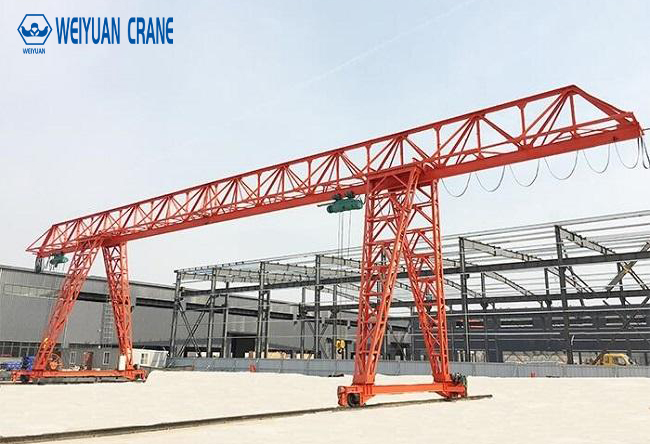
The runway is the horizontal track structure the crane travels along. On a double-girder or single-girder gantry crane, the end trucks carry wheels that run on rails fixed to the runway beams. As the crane moves, the runway carries the full weight of the crane, the load, and all the dynamic forces that lifting and travel create.
The load path
Every load the crane lifts follows a defined path down to the ground. Understanding this path is the foundation of runway design:
- The hoist lifts the load, applying force to the trolley.
- The trolley transfers that force to the bridge girder.
- The bridge girder carries the force to the end trucks.
- The end truck wheels press down on the rails.
- The rails transfer the wheel loads into the runway beams.
- The runway beams carry the loads to their support columns or brackets.
- The columns transfer everything to the foundation.
The runway beam sits at step six — the last structural member before the load reaches the columns. It must carry vertical wheel loads, lateral forces from crane travel and load swing, and longitudinal forces from acceleration and braking. All three act at once, and the beam must handle every combination without excessive deflection or stress.
Three force directions
- Vertical load: the crane dead weight plus the lifted load plus the dynamic impact factor. This is the largest force and drives beam depth selection.
- Lateral load: perpendicular to travel, from load swing, skewing, and trolley acceleration. CMAA takes this as a percentage of the lifted load plus trolley weight, typically around 20% distributed to the runway.
- Longitudinal load: parallel to travel, from crane acceleration and braking. Usually taken as about 10% of the maximum wheel loads.
A runway beam designed only for vertical load — and there are many of them out there — will flex sideways, twist, and crack under the lateral and longitudinal forces it was never sized to carry.
Part 2: Runway Beam Types
The beam section you choose sets the runway’s stiffness, its load capacity, and its cost. Three main types cover nearly all industrial gantry crane runways.
Type 1: Standard I-Beam (S-Shape)
A rolled steel I-beam with narrow, tapered flanges. This is the lightest and lowest-cost option, suited to short spans and light cranes.
Practical range: cranes up to around 5 tonnes on spans up to roughly 6 metres.
Strengths: low cost, readily available, simple to install.
Weakness: the narrow flanges give poor lateral stiffness. Under the crane’s side loads, a plain I-beam tends to twist (lateral-torsional buckling). Above light duty, it needs lateral bracing or a cap channel welded to the top flange to resist the sideways forces.
Type 2: Wide Flange Beam (W-Shape / H-Beam)
A rolled beam with wide, parallel flanges. The broader top flange gives far better lateral stiffness than a standard I-beam, making it the workhorse of medium-duty runways.
Practical range: cranes from 5 to 20 tonnes on spans up to roughly 9 to 12 metres.
Strengths: good balance of vertical and lateral stiffness, wide flange supports the rail well, widely available in many sizes.
Common upgrade: for heavier duty, weld a channel or cap plate to the top flange (a “capped” wide flange). This adds lateral stiffness and strengthens the flange against the concentrated wheel load without jumping to a full box girder.
Type 3: Box Girder (Fabricated)
A fabricated hollow rectangular section built from steel plates. The closed shape gives outstanding resistance to both bending and torsion, making it the choice for heavy loads, long spans, and high duty cycles.
Practical range: cranes above 20 tonnes, long spans, and Class D to F service.
Strengths: highest strength-to-weight ratio, excellent torsional stiffness, custom-sized to the exact load and span, ideal where lateral forces are high.
Trade-off: highest fabrication cost and more complex to build. Justified when a rolled section cannot meet the deflection or stress limits, or when the span and load demand a custom solution.
Selection rule of thumb:
- Light crane, short span → standard I-beam (braced if needed)
- Medium crane, medium span → wide flange, capped for heavier duty
- Heavy crane, long span, high duty → box girder
Part 3: Deflection Limits and Span-to-Depth Ratios
Deflection — how much the beam sags under load — is often the governing design criterion for a runway beam, more so than stress. A beam can be strong enough to carry the load and still deflect too much for a crane to run smoothly.
Why deflection matters more than strength
The crane wheels must run on a level, straight track. When a runway beam deflects under the wheel load, it creates a shallow valley the crane must climb out of as it travels. This forces the travel motor to work harder, wears the wheels unevenly, and — over thousands of cycles — fatigues the beam and its connections. Excessive deflection also lets the load swing more, reducing positioning accuracy.
CMAA vertical deflection limits
CMAA Specification No. 70 sets the vertical deflection limit for runway beams under the maximum wheel loads (without impact):
Vertical deflection ≤ L / 600
Where L is the runway span between column supports. For a 9-metre span:
Maximum deflection = 9,000 mm ÷ 600 = 15 mm
Some heavy-duty or precision applications tighten this to L/800 or L/1000. For high-cycle Class E and F cranes, the stricter limit protects against fatigue.
Lateral deflection limit
The runway beam must also resist sideways deflection from the crane’s lateral forces:
Lateral deflection ≤ L / 400 (of the top flange, under the lateral load)
Lateral deflection is often the reason a plain I-beam fails a runway check even when its vertical strength is adequate — the narrow flange simply cannot resist the side load.
Span-to-depth ratio
A quick sanity check before detailed calculation: the beam depth should fall within a workable ratio of its span.
Practical span-to-depth ratio: L/15 to L/18 for runway beams.
For a 9-metre span:
Minimum practical depth = 9,000 ÷ 18 = 500 mm
Preferred depth = 9,000 ÷ 15 = 600 mm
A beam shallower than L/20 will almost always fail the deflection check, no matter how strong its material. Start near L/15 to L/18 and confirm with the full deflection calculation.
Deflection formula
For a simply supported beam with a moving wheel load, the maximum deflection under a central point load is:
δ = P L³ ÷ (48 E I)
Where:
- δ = deflection (mm)
- P = wheel load (N)
- L = span (mm)
- E = modulus of elasticity of steel (≈ 200,000 N/mm²)
- I = moment of inertia of the beam section (mm⁴)
For twin wheel loads at the actual wheel spacing, the deflection is calculated by superposition at the worst-case wheel position. The moment of inertia I is the value you increase — by choosing a deeper section — to bring the deflection within the limit.
Part 4: Lateral Bracing and Stiffener Requirements
A runway beam does not work alone. Two supporting details — lateral bracing and web stiffeners — keep it stable and prevent the local failures that plague under-detailed runways.
Lateral bracing
Lateral bracing restrains the beam’s top flange against sideways buckling and against the crane’s lateral forces. Without it, a long or narrow beam can twist and buckle sideways well below its vertical capacity.
Common bracing methods:
- Cap channel: a steel channel welded to the top flange, turning it into a much stiffer section against lateral load. Simple and effective for wide flange runways.
- Horizontal lacing or a lateral truss: a bracing system running alongside the beam, tying the top flange back to the columns or to a parallel member. Used on longer spans and heavier duty.
- Tie-backs to the building structure: where an existing frame is available, the top flange can be braced back to it at intervals.
Bracing intervals depend on the beam’s unbraced length and the lateral load, but a braced top flange is essential once the crane moves beyond light duty. The lateral force is real, continuous, and cyclic — the bracing must be designed for it, not added as an afterthought.
Web stiffeners
The crane wheel applies a concentrated load to a small area of the beam’s top flange, which transfers into the thin web directly below. Without reinforcement, the web can buckle or cripple under this concentrated load.
Bearing stiffeners — vertical plates welded to the web — are required at:
- Each support point (over the columns), where the full reaction passes into the column.
- Points of high concentrated load where web crippling checks fail.
Intermediate stiffeners at regular intervals along the web are used on deep, slender webs to prevent shear buckling. The need for them depends on the web’s depth-to-thickness ratio and the applied shear.
The rule is simple: wherever a concentrated force enters or leaves the beam, check the web for crippling and buckling, and add a stiffener if the check fails. A missing bearing stiffener over a column is one of the most common — and most damaging — runway detailing errors.
Part 5: End Stops and Bumper Design
At each end of the runway, the crane must be stopped safely if it travels past its normal limit. End stops and bumpers are not optional extras — they are a required safety component, and a poorly designed one transfers a severe impact straight into the runway structure.
End stops
An end stop is a rigid steel structure fixed to the end of each runway beam. It physically prevents the crane end truck from running off the rail. The end stop must be strong enough to absorb the crane’s kinetic energy at full travel speed, transferred through the bumper.
Bumpers
The bumper sits between the crane end truck and the end stop, absorbing the impact energy so the shock is not delivered as a sudden spike. Two common types:
- Rubber or polyurethane bumpers: absorb energy through elastic compression. Simple, low maintenance, suited to lighter and lower-speed cranes.
- Hydraulic (spring-return) buffers: absorb energy through controlled fluid damping. Used on heavier and faster cranes, where they cushion the impact over a longer stroke and greatly reduce the peak force.
Sizing the impact
The energy the bumper must absorb comes from the crane’s motion:
Kinetic energy E = ½ m v²
Where:
- m = crane mass (kg)
- v = travel speed at impact (m/s) — CMAA commonly uses a design impact speed of 40% to 50% of rated travel speed, assuming the drive has already begun to slow
The bumper is selected so its energy-absorption rating meets or exceeds this value, and the end stop is designed for the resulting peak force. A common error is sizing the bumper for full rated speed or, worse, omitting the energy calculation entirely — leaving an end stop that fails on the first hard contact.
Part 6: Common Runway Design Errors
Most runway problems come from a handful of repeated mistakes. Knowing them upfront is the cheapest insurance you can buy.
Error 1: Undersized Beams
The beam is selected on vertical strength alone and passes the stress check, but its moment of inertia is too small to meet the deflection limit. The runway sags under the crane, the wheels wear unevenly, and the beam fatigues over time.
Prevention: always check deflection against L/600 vertical and L/400 lateral, not just stress. Start with a span-to-depth ratio of L/15 to L/18 and confirm with the deflection calculation.
Error 2: Missing or Inadequate Lateral Bracing
The beam is sized for vertical load but the top flange is left unbraced. Under the crane’s lateral forces, the flange twists and buckles sideways, and the beam fails well below its vertical capacity.
Prevention: brace the top flange for the full lateral load once the crane moves beyond light duty. Use a cap channel, lateral truss, or tie-backs, and design the bracing for the cyclic side force — do not treat it as optional.
Error 3: Inadequate End Stops
The end stop or bumper is undersized, or the impact energy was never calculated. When the crane over-travels, the impact damages the end stop, the end truck, or the runway beam itself.
Prevention: calculate the kinetic energy at the design impact speed and select a bumper rated to absorb it. Design the end stop for the resulting peak force. Never install an end stop without the energy calculation behind it.
Error 4: Missing Bearing Stiffeners
The beam has no bearing stiffeners over the support columns. The concentrated reaction crushes the web, which buckles or cracks at the support point over time.
Prevention: add bearing stiffeners at every support and at any point where the web crippling check fails. Check the web wherever a concentrated force enters or leaves the beam.
Error 5: Mismatched or Discontinuous Runway Beams
The two runway beams are different sections, or a single runway is spliced with a weak connection that creates a step or a soft spot. The crane runs unevenly across the mismatch, loading one side more than the other.
Prevention: use identical beam sections on both runways, and design any splice as a full-strength continuous connection. Both rails must behave the same way under load.
Part 7: CMAA Tolerances and Alignment Before Crane Mounting
After the runway beams and rails are installed — and before the crane is mounted — a full alignment survey must confirm the runway is within tolerance. Mounting a crane onto an out-of-tolerance runway locks in wear and misalignment from day one.
CMAA Specification No. 70 runway tolerances
- Track gauge (span between rail centrelines): ±3 mm from nominal at any point.
- Elevation difference between the two rails at any cross-section: ±10 mm maximum.
- Rate of elevation change: the elevation should not change by more than a defined amount over a given length — check that no local high or low spot creates a sharp grade.
- Straightness (horizontal, individual rail): ±2 mm in any 10-metre length.
- Waviness (vertical, individual rail): ±2 mm in any 10-metre length.
- Rail joint step: ≤ 0.5 mm vertical step at any joint.
Alignment survey procedure
- Survey the runway with an optical level or laser after rail installation, before the crane is lifted into place.
- Record track gauge, elevation, straightness, and joint steps at regular intervals along the full length.
- Compare every measurement against the CMAA tolerances above.
- Correct any out-of-tolerance point — shim, grind, or realign — before mounting the crane.
- Document all readings in a runway survey report and retain it permanently as the as-installed baseline.
The reason for the sequence is cost. Correcting a runway before the crane is mounted is straightforward. Correcting it afterward means working around or removing a multi-tonne crane, at many times the labor cost. Any measurement outside tolerance is corrected now, not later.
Frequently Asked Questions
Q: What deflection limit applies to a gantry crane runway beam?
CMAA Specification No. 70 sets the vertical deflection limit at L/600 of the span under maximum wheel loads without impact, and the lateral deflection limit at roughly L/400 of the top flange under lateral load. Heavy-duty or precision cranes often tighten the vertical limit to L/800 or L/1000. Deflection, not stress, is frequently the governing criterion — a beam can be strong enough yet still deflect too much for the crane to run smoothly.
Q: How do I choose between an I-beam, wide flange, and box girder for a runway?
Match the section to the load, span, and duty. A standard I-beam suits light cranes on short spans but usually needs lateral bracing. A wide flange beam covers most medium-duty runways and can be capped with a channel for heavier work. A fabricated box girder is the choice for heavy loads, long spans, and high duty cycles, thanks to its excellent bending and torsional stiffness. As a rule, move up a type whenever the deflection or lateral check fails.
Q: Why does a runway beam need lateral bracing?
A crane applies significant lateral forces to the runway from load swing, skewing, and trolley acceleration — commonly around 20% of the lifted load plus trolley weight. A narrow, unbraced top flange twists and buckles sideways under these forces, often failing well below its vertical capacity. Lateral bracing — a cap channel, lateral truss, or tie-backs — restrains the top flange and carries the side load safely. It is essential once the crane moves beyond light duty.
Q: Where are stiffeners required on a runway beam?
Bearing stiffeners are required at every support point over the columns, where the full reaction passes into the column, and at any concentrated load point where the web crippling check fails. Intermediate stiffeners are added along deep, slender webs to prevent shear buckling, depending on the web’s depth-to-thickness ratio. The principle is simple: wherever a concentrated force enters or leaves the beam, check the web and add a stiffener if the check fails.
Q: How are end stops and bumpers sized?
Size them from the crane’s kinetic energy, E = ½ m v², where m is the crane mass and v is the design impact speed — CMAA commonly uses 40% to 50% of rated travel speed. Select a bumper whose energy-absorption rating meets or exceeds this value, and design the end stop for the resulting peak force. Rubber or polyurethane bumpers suit lighter, slower cranes; hydraulic buffers suit heavier, faster ones. Never install an end stop without the energy calculation behind it.
Q: What span-to-depth ratio should a runway beam have?
A practical starting range is L/15 to L/18. For a 9-metre span, that gives a beam depth of roughly 500 to 600 mm. A beam shallower than about L/20 will almost always fail the deflection check regardless of its material strength. Use the ratio as a first sizing guide, then confirm the final section with the full deflection calculation against the L/600 vertical limit.
Q: What alignment tolerances must the runway meet before mounting the crane?
Per CMAA Specification No. 70: track gauge within ±3 mm, elevation difference between rails within ±10 mm at any cross-section, individual rail straightness within ±2 mm in any 10 metres, waviness within ±2 mm in any 10 metres, and rail joint steps no greater than 0.5 mm. Survey the runway and correct every out-of-tolerance point before the crane is mounted — fixing it afterward costs many times more.