


Gantry Crane Structure & Foundation Guide
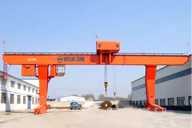
Introduction
A precast concrete plant I worked with had specified their gantry crane perfectly. Right type, right capacity, right duty class — the selection work done properly, the way Part 1 of this series lays out. They ran a 32-tonne double-girder full gantry across their casting yard, and on paper it was the right machine for the job. It even was the right machine. The trouble was everything underneath it.
The rails had been laid on a foundation sized for the crane’s static wheel loads, but nobody had run the numbers for the dynamic impact of lifting a green casting off its bed, or for the concentrated point loads the wheels drove into the rail on every pass. Within the first year the rail heads had started to spall, one foundation edge had settled a few millimeters, and the crane — running true at commissioning — had begun to skew. By month eighteen the maintenance crew was regrinding rail, replacing wheels worn into a wedge, and chasing travel motors that kept tripping on overcurrent. The crane never failed. The structure beneath it did, one small tolerance at a time.
That’s the pattern with gantry cranes. The machine gets all the attention because it’s the visible, expensive part — but a gantry stands on its own legs and drives its entire weight into the ground through a handful of wheels and two rails. If the girders flex too much, the legs rack under load, the rails aren’t sized for the wheel loads, or the foundation settles, the best crane in the catalog will grind itself apart on a structure that couldn’t hold it true. The structure isn’t a footnote to the crane. It is the crane, as far as service life goes.
This is Part 2 of our three-part gantry crane series. Part 1 covered selection — types, girder configuration, span, capacity, duty class, and site conditions. Here we get into the part that decides whether that well-chosen crane actually delivers its service life: the girder and leg structural design that carries the load, the rail selection and fixing that carries the wheels, the foundation engineering that carries everything into the ground, the alignment tolerances that keep the crane running true, the wheel-rail mechanics that turn small errors into big repair bills, and the thermal expansion that quietly wrecks a rigidly fixed long rail. Part 3 will close the series on operation, maintenance, and inspection.
What you’ll take away:
- How single- and double-girder gantries carry load differently, and why leg rigidity matters as much as girder strength
- How to size and fix the rail so it carries the wheel loads without spalling or drifting
- How to engineer a foundation against dynamic wheel loads, not just static weight
- The gauge, elevation, and straightness tolerances you must hold your installer to
- How a few millimeters of misalignment cause flange wear, rail wear, and motor overload
- Why a long rail needs room to expand — and what happens when it doesn’t
- 2026 pricing so the civil and structural scope doesn’t ambush your budget
Part 1: Girder and Leg Structural Design
A gantry crane is a portal frame on wheels. The bridge girder spans the working width, the legs carry the bridge down to the rails, and the whole assembly has to stay rigid while a moving load tries to bend it, twist it, and rack it sideways. Understanding how the load travels through that frame explains why some gantries run true for decades and others wobble their way through an early replacement.
How the Girder Carries the Load
When the hoist lifts a load at mid-span, the girder bends. That bending — the vertical sag under load — is the single biggest driver of girder size. A gantry girder isn’t sized to hold the load; almost any steel section can do that. It’s sized to hold the load without deflecting past its allowable limit, because excessive deflection makes the trolley run downhill toward mid-span, stresses the connections, and makes precise placement impossible.
Deflection grows sharply with span. Double the span and the deflection under the same load rises far faster than double, which is why long-span gantries need disproportionately deep, heavy girders. The design limit is usually expressed as a fraction of the span — a common target is that mid-span deflection under rated load stays within roughly 1/700 to 1/1000 of the span, depending on the duty and the standard applied.
Single-Girder vs. Double-Girder Forces
The two configurations carry the load along different paths, and that changes both the stresses and the failure modes.
   SINGLE GIRDER                    DOUBLE GIRDER

   ┌──────────────────┐            ┌────[trolley]────┐
   │   [hoist below]  │            ╞═════════════════╡
   │        │         │            │        │        │
   ▟        ▼         ▙            ▟        ▼        ▙
   █                  █            █                 █
  ═╪══════════════════╪═          ═╪═════════════════╪═
Single-girder hangs the hoist below one main girder. The load line sits off-center from the girder’s shear center, which means every lift applies not just bending but torsion — a twisting force that tries to roll the girder over. That’s why single-girder sections are often box girders or beams with reinforced top flanges: the closed section resists twist far better than an open one. Single-girder gantries stay economical up to roughly 20 tonnes precisely because keeping torsion manageable gets expensive as the load climbs.
Double-girder runs the trolley on top, between two girders, so the load line sits between the two webs. The load splits between the girders and the torsion largely cancels — each girder mostly sees clean vertical bending. This is why double-girder configurations handle the heavy capacities and long spans: the two-girder arrangement is inherently stiffer and better balanced, and it recovers hook height by letting the hook pull up between the girders rather than hang below a single one.
Why Leg Rigidity Matters as Much as the Girder
Buyers focus on the girder and forget the legs — but the legs are where a lot of gantry trouble actually lives. The legs carry the bridge reactions down to the wheels, and they have to resist three things at once:
- Vertical load — the bridge, trolley, load, and dynamic impact pressing straight down.
- Lateral thrust — the sideways force when the trolley or the whole crane accelerates and brakes, trying to rack the portal frame into a parallelogram.
- Longitudinal thrust — the force along the rails when the gantry itself starts and stops.
A gantry that’s stiff vertically but flexible sideways will rack — the top of the frame leads or lags the bottom as the crane travels, which skews the wheels against the rails and drives the flange wear we’ll come to in Part 5. This is why many full gantries use a rigid leg on one side and a flex leg (or pin-connected leg) on the other: the rigid leg holds the frame square and takes the lateral and longitudinal forces, while the flex leg allows for small differences in rail gauge and thermal movement without forcing the structure to fight itself.
   RIGID LEG                    FLEX / PIN LEG
   (takes lateral +             (allows small gauge
    longitudinal force)          & thermal movement)

   ┌──┐                         ┌──┐
   │  │  ← braced, stiff        │  │  ← pinned, flexible
   │  │                         │╲╱│
   █                            █
  ═╪═                          ═╪═
Mini-takeaway: the girder is sized by deflection, not just strength, and the legs are sized to resist racking, not just to hold the bridge up. A gantry that’s rigid one way and flexible another skews on its rails — so the whole portal frame, girder and legs, has to be designed as one system. Ask your supplier for the deflection limit and how the frame handles lateral thrust; a vague answer is a warning sign.
Part 2: Rail Selection and Fixing Methods
The rail is the interface between a machine that can weigh dozens of tonnes and the foundation that carries it. Get the rail section, its fixing, and its support right and the crane rolls true for decades. Get them wrong and you undermine even a perfectly built gantry — the rail spalls, the wheels pound, and the alignment drifts.
Sizing the Rail to the Wheel Load
Rail size follows the wheel load, not the crane’s total weight. Each wheel concentrates a share of the dead weight, the lifted load, and the dynamic impact onto a contact patch the size of a coin. If the rail is under-sized for that concentrated load, the rail head deforms and spalls — flakes and cracks under the repeated contact stress — exactly the failure that started the precast plant’s spiral.
Rail options range from lighter crane rail sections for smaller gantries, up through heavy crane rail (the A-series or DIN sections) and even standard train rail for the largest, heaviest-duty machines. Your supplier specifies the rail from the crane’s wheel loads and wheel diameter — a larger wheel spreads the contact over more rail, which lets a given rail carry more.
Don’t be tempted to substitute a lighter, cheaper rail to trim the quote. The saving vanishes the first time you have to regrind or replace a rail head that couldn’t carry the load — and it takes a set of wheels with it.
How the Rail Is Fixed Down
The way the rail attaches to its foundation beam affects both alignment stability and how easy it is to correct later. Two broad approaches dominate:
- Rail clips on a sole plate. Clips bolt the rail down firmly while allowing controlled movement along the rail’s length for thermal expansion. This is the flexible, maintainable choice: clips can be loosened, the rail re-aligned, and the clips re-tightened. It’s the standard for most gantry rails because it keeps future alignment corrections practical.
- Welded or grouted-in rail. Used where a very rigid, permanent fixing is wanted. The trade-off is that it’s far harder to adjust later, so the alignment at installation has to be exact from the start — and, as Part 6 covers, a rigidly fixed long rail with no room to expand invites thermal trouble.
Continuous, Even Support Is Non-Negotiable
Whatever the fixing method, the rail needs continuous, even support beneath it. A rail bedded on high spots with gaps between them concentrates the wheel load onto those points, and the rail flexes and fails early. Even support — a properly leveled sole plate on a sound foundation beam — spreads the wheel loads the way the design intends and keeps the rail head from working loose.
For outdoor gantries, the rail fixing also has to survive weather: galvanized or otherwise protected clips and fasteners, because a corroded clip that lets the rail creep is the start of an alignment problem.
Mini-takeaway: size the rail to the wheel load, not the crane weight; fix it with clips that allow thermal movement and future re-alignment; and bed it on continuous, even support. A rail is cheap relative to the wheels and downtime a bad rail costs.
Part 3: Foundation Engineering for Gantry Wheel Loads
A gantry crane drives its entire existence into the ground through two rails and a handful of wheels. The foundation is what carries that concentrated force without settling, cracking, or letting the rails drift. It’s also where the precast plant’s real mistake lived: the foundation was sized for the static crane, not the crane in motion under load.
The Load Is Bigger Than the Crane Weighs
The foundation doesn’t just carry the dead weight of the crane and the rated load standing still. It has to carry them moving, with two additions that catch buyers out:
- Dynamic impact. When the hoist snatches a load off the ground, or the load swings, the structure sees a force greater than the static weight. Codes add a dynamic factor — commonly 15 to 25% for electric hoists — on top of the static wheel load. A 32-tonne crane lifting 32 tonnes can hand the rail and foundation the equivalent of considerably more at the moment of lift.
- Concentrated point loads. All that weight arrives through a few small wheel contact patches, not spread evenly. The foundation beam under the rail has to spread those point loads out to the soil below without over-stressing any one spot.
Design the foundation to the static number alone — as the precast plant’s contractor did — and you’ve under-built it for the job it actually does.
What the Foundation Has to Do
A gantry rail foundation, typically a reinforced concrete beam or strip footing running the full length of each rail, has three jobs:
- Carry the wheel loads to the soil without exceeding the soil’s bearing capacity — established by a geotechnical assessment, not assumed.
- Resist settlement, especially differential settlement, where one part of the foundation sinks more than another. Differential settlement is what throws the rails out of level and starts the skewing spiral.
- Hold the rails in gauge and alignment over the crane’s whole life, through load cycles, temperature swings, and — outdoors — frost and drainage.
Why Differential Settlement Is the Silent Killer
Uniform settlement — the whole foundation sinking evenly by a few millimeters — is largely harmless; the crane goes down with it and keeps running true. Differential settlement is the problem. When one rail, or one section of a rail, settles more than the rest, the runway goes out of level and the crane starts to skew. This is exactly what happens on the variable or filled ground common to yards and terminals, and it’s why a geotechnical assessment isn’t optional on a gantry foundation.
Outdoors, two more factors attack the foundation:
- Frost heave. In cold climates, water in the soil freezes and expands, lifting and cracking a foundation that doesn’t extend below the frost line.
- Drainage. Water pooling around or under the foundation softens the supporting soil and accelerates settlement. Designed drainage keeps water away from the base.
Mini-takeaway: design the foundation for the crane in motion — static load plus dynamic impact plus concentrated wheel loads — on a geotechnical basis, and detail it to resist differential settlement, frost, and poor drainage. Get the maximum and minimum wheel loads from your supplier and hand them to a structural and geotechnical engineer before you pour. The foundation is the cheapest place to prevent the most expensive failure.
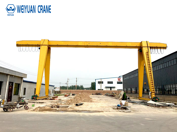
Part 4: Geometric Alignment Tolerances
Even a perfectly engineered gantry crane on a sound foundation will wear rapidly and skew if the two rails aren’t laid — and kept — within tolerance. Crane wheels are rigid steel running on rigid rail, with almost no ability to absorb misalignment, so a runway that’s a few millimeters out translates that error straight into wear. These are the numbers you hold your installer to, and demand documented proof of before you accept the runway.
The Four Critical Tolerances
Four geometric tolerances govern a gantry runway, drawn from CMAA Specification No. 70 and the MBMA crane building guidance most manufacturers reference.
                 [Gauge G — center to center]
   |<─────────────────────────────────────────────>|
   ┌──┐                                          ┌──┐
   │  │  Rail A                          Rail B  │  │
   └──┘                                          └──┘
   ════                                          ════
     ▲                                             ▲
     └──────────── Elevation delta (ΔE) ───────────┘
| Tolerance | What it controls | Typical limit |
|---|---|---|
| Gauge (G) | Center-to-center distance between the two rails | ±3 mm (±1/8″) for spans under 15 m; ±6 mm (±1/4″) max over 15 m |
| Elevation deviation (ΔE) | Vertical height difference between opposing rails at any cross-section | Max 10 mm (3/8″) total; rate-of-change limit ~2 mm per 3 m |
| Straightness | Lateral deviation of a rail from its theoretical centerline | ±3 mm (±1/8″) over a standard 10 m length |
| Rail joint offset | Vertical or horizontal mismatch at rail joints | Max 0.5 mm (1/64″) |
Gauge — Keep the Rails Parallel
Gauge is the distance between the two rails, center to center. Because the gantry’s legs are a fixed distance apart, the rails have to match that distance along the whole runway. If the gauge widens or narrows, the wheels bind or skew. Hold it to ±3 mm under 15 m spans and ±6 mm maximum over 15 m — the wider tolerance on long spans reflects the small flex a long bridge can absorb, not permission to be sloppy.
Elevation — Keep the Rails Level With Each Other
Elevation deviation is the vertical height difference between the two rails at any cross-section. If one rail sits higher than the other, the crane runs on a twist, throwing extra load onto the low-side wheels. Two limits apply: a total difference of no more than 10 mm, and a rate-of-change limit — no abrupt local dips or humps — of roughly 2 mm per 3 meters. That second limit is the one people forget, and it’s the one that pounds wheels.
Straightness — Keep Each Rail Running True
Straightness is how far each rail wanders sideways from its theoretical centerline — hold it to ±3 mm over a standard 10 m length. A rail that snakes left and right forces the crane to constantly correct its path, driving lateral load into the wheel flanges.
Rail Joint Offset — The Tightest Tolerance
Where rail sections meet, any vertical or horizontal step must not exceed 0.5 mm. This is the tightest number on the list because a step at a joint is a hammer blow delivered to the wheel on every pass — dynamic wheel pounding that fatigues the wheel, the rail, and the foundation around the joint.
Mini-takeaway: make a documented alignment survey against all four tolerances — gauge, elevation, straightness, joint offset — a condition of acceptance in your purchase order, with final payment tied to it. It’s the cheapest insurance you can buy on a long-lived, high-value asset.
Part 5: Wheel-Rail Contact Mechanics — How Small Errors Become Big Bills
To see why those millimeter tolerances matter, you have to understand what happens where the wheel meets the rail. This is where alignment error gets converted into wear, heat, and wasted energy — and where the precast plant’s crane quietly ate itself.
How a Gantry Is Supposed to Track
Ideally, a crane wheel rolls along the top of the rail with its flange — the raised lip on the wheel — sitting just clear of the rail’s side. The flange is a guide, not a bearing surface. When the runway is aligned and the portal frame is square, the flanges rarely touch, the wheels roll clean, and the crane tracks straight with minimal resistance.
What Misalignment Does
Introduce a few millimeters of gauge error, an out-of-level rail, or a racking leg (from Part 1), and the crane can no longer roll cleanly — it skews, cocking at a slight angle to the rails as it travels, like a supermarket trolley with a bad caster. Once it skews, the mechanics turn destructive fast:
- Flange wear. The skewing crane forces its wheel flanges hard against the rail sides. Those flanges — meant only to guide — now carry lateral load and grind against the steel, wearing into the wedge shape that’s the classic fingerprint of a misaligned runway.
- Rail wear. The same grinding wears the sides of the rail heads, so you consume two components at once — wheels and rail.
- Motor overload. A skewing crane fights friction the whole length of the runway. The travel motors work harder, draw more current, run hotter, and trip on overload — and even before anything fails, you pay for it in higher energy consumption on every trip.
- Structural fatigue. The lateral forces from skewing feed back into the legs, girders, and foundation, adding cyclic stress the structure wasn’t meant to carry continuously.
Why It Compounds
Here’s the vicious part, and the reason the precast plant went from a few millimeters of settlement to a full wheel-and-rail replacement: misalignment causes uneven wear, and uneven wear worsens the misalignment. A wheel worn into a wedge tracks even more crookedly, which accelerates the wear, which worsens the tracking. A small initial error snowballs. Catching it early — while it’s still an alignment adjustment or a re-shim — is dramatically cheaper than catching it after the wheels and rail are gone.
Mini-takeaway: the flange is a guide, not a load-bearing surface — when it starts carrying lateral load, the crane is skewing and the clock is running. Metallic shavings along the rail, a screech during travel, wedge-worn wheels, or travel motors tripping all point to the same suspect: alignment. Act on them while the fix is still cheap.
Part 6: Thermal Expansion — Why a Long Rail Needs Room to Move
Steel rail expands and contracts with temperature. Over a short indoor gantry runway this is minor. Over a long runway — especially an outdoor one exposed to seasonal swings and direct sun — the movement becomes significant, and a rail with nowhere to go will destroy its own alignment.
The Physics, in Practical Terms
Steel expands roughly 12 micrometers per meter for every degree Celsius. That sounds tiny until you scale it up. A 100-meter outdoor gantry runway swinging through a 40°C range between a cold winter night and a hot summer afternoon moves on the order of 48 millimeters over its length. That’s not a rounding error — it’s several times the alignment tolerances from Part 4.
What Happens When the Rail Can’t Move
Fix a long rail down rigidly — welded or grouted with no expansion provision — and that movement has nowhere to go. The result:
- The rail buckles sideways or lifts, throwing itself straight out of straightness and elevation tolerance.
- The fixings tear as the rail pushes against them with enormous force.
- Even if it holds, the rail builds up internal stress that fatigues it and the foundation.
This is the main reason clipped rail — which permits controlled sliding along its length — is strongly preferred over rigidly grouted rail on any long or outdoor run. The clips hold the rail down and in line while letting it grow and shrink freely.
Designing for Thermal Movement
Managing thermal expansion on a gantry runway comes down to a few provisions your supplier should account for:
- Expansion gaps at rail joints, sized so the rail can grow into them without the joint closing up and forcing a buckle.
- Clip fixing that clamps the rail vertically and laterally but permits longitudinal sliding.
- The flex leg on the crane itself (Part 1), which absorbs small changes in effective gauge as the rails and structure expand differently, so the portal frame doesn’t fight the movement.
When you review a gantry runway design, confirm the fixing method and joint detailing account for thermal movement appropriate to your rail length and climate. It’s an easy detail to overlook indoors and an expensive one to correct on a long outdoor runway.
Mini-takeaway: a long rail must be free to expand, or it will wreck its own alignment. Specify clipped fixing with expansion provision on any long or outdoor runway, and make sure the crane’s flex leg is there to absorb the gauge changes that come with it.
Part 7: 2026 Price Reference for Gantry Structure & Foundation Works
Use these as planning figures to build a realistic budget for the structural and civil scope — the part of a gantry project most likely to be under-quoted or excluded. Actual costs vary with rail length, crane size, soil conditions, site access, and region. Always get a site-specific quote, but budget against these ranges so the foundation and rail work don’t ambush your project.
| Structure / foundation element | Scope | 2026 planning range (USD) |
|---|---|---|
| Crane rail supply & installation | Rail, clips, sole plates, fixing (per rail metre) | $250 – $1,000 per linear metre |
| Reinforced rail foundation beam | Concrete beam/footing per rail line, per metre | $400 – $1,500 per linear metre |
| Geotechnical assessment | Soil investigation & bearing report | $3,000 – $15,000 |
| Commissioning alignment survey | Professional runway survey to CMAA/MBMA tolerance | $3,000 – $12,000 |
| Periodic alignment re-check | Recurring survey against baseline | $2,500 – $8,000 |
| Runway re-alignment (shim / adjust) | Correcting drifted alignment early | $5,000 – $25,000 |
| Rail regrind or replacement | Late-stage fix after wear/spalling damage | $15,000 – $70,000+ |
| Wheel-set replacement (per set) | Wheels + labor + re-alignment | $5,000 – $30,000 |
| Outdoor rail package | Galvanized fixings, expansion detailing, drainage | +15% to +30% on rail works |
Two budget realities worth flagging:
- The foundation and rail can rival the crane. On any gantry — especially a heavy or long-span one on marginal ground — the reinforced foundation and rail works are a genuine civil cost that can approach the price of the crane itself. A crane quote that excludes them isn’t cheaper; it’s incomplete.
- Early correction beats late repair by a wide margin. A geotechnical assessment and a commissioning alignment survey together cost a few percent of the project, and they prevent the differential settlement and skewing that lead to a five-figure rail regrind and wheel-set replacement — exactly the bill the precast plant paid for skipping the dynamic-load foundation design.
Procurement tip: when you compare gantry quotes, confirm the civil and structural scope line by line — rail supply and fixing, foundation beam, geotechnical work, and the commissioning alignment survey. A cheap headline number often excludes the foundation or bundles the survey as an optional extra. Normalize every quote to the same structural scope, and make the documented alignment survey a condition of acceptance with payment tied to it.
Frequently Asked Questions
Q: What actually determines the size of a gantry crane girder?
A: Deflection, not raw strength. Almost any adequate steel section can hold the rated load — the girder is sized so it holds that load without sagging past its allowable deflection limit, commonly a fraction of the span in the range of 1/700 to 1/1000. Excessive deflection makes the trolley run downhill toward mid-span, stresses the connections, and ruins placement accuracy. Deflection grows sharply with span, which is why long-span gantries need disproportionately deep, heavy girders. Single-girder designs also have to resist torsion, because the hoist hangs off-center below the girder; double-girder designs largely cancel that twist by running the trolley between two girders.
Q: Why do gantry cranes often have one rigid leg and one flexible leg?
A: To keep the portal frame square without forcing it to fight small variations in the runway. The rigid leg holds the frame stiff and takes the lateral and longitudinal thrust from acceleration and braking, so the crane doesn’t rack into a parallelogram and skew its wheels. The flex (or pin-connected) leg allows small differences in rail gauge and, importantly, the thermal expansion of a long runway, so the structure can accommodate that movement instead of buckling a rail or tearing a fixing. A frame that’s rigid one way and flexible another is exactly what lets a gantry stay aligned across temperature swings and minor settlement.
Q: How do I size the rail and foundation for my gantry crane?
A: Both follow the wheel loads, not the crane’s total weight — and the wheel loads must include dynamic impact, not just static weight. Get the maximum and minimum wheel loads from your supplier during specification. The rail section is sized so its head carries the concentrated wheel-contact stress without spalling; under-size it and the rail flakes and fails. The foundation — a reinforced concrete beam per rail line — is sized against a geotechnical bearing report to carry those wheel loads plus a dynamic factor (commonly 15–25% for electric hoists) without exceeding the soil’s capacity, and detailed to resist differential settlement. Hand the wheel loads to a structural and geotechnical engineer before you commit to a layout.
Q: What alignment tolerances should I hold my installer to?
A: Four, from CMAA Spec 70 and MBMA guidance. Gauge (center-to-center rail spacing): ±3 mm for spans under 15 m, ±6 mm maximum over 15 m. Elevation deviation (height difference between the two rails): 10 mm total maximum, with a rate-of-change limit around 2 mm per 3 m so there are no abrupt dips or humps. Straightness (lateral wander of each rail): ±3 mm over a standard 10 m length. Rail joint offset (step at joints): 0.5 mm maximum, the tightest of the four, because a step hammers the wheel on every pass. Demand a documented alignment survey against all four as a condition of acceptance, and require periodic re-checks against that baseline.
**Q: Do I really need to worry about thermal