


Jib Crane for Manufacturing Workstations
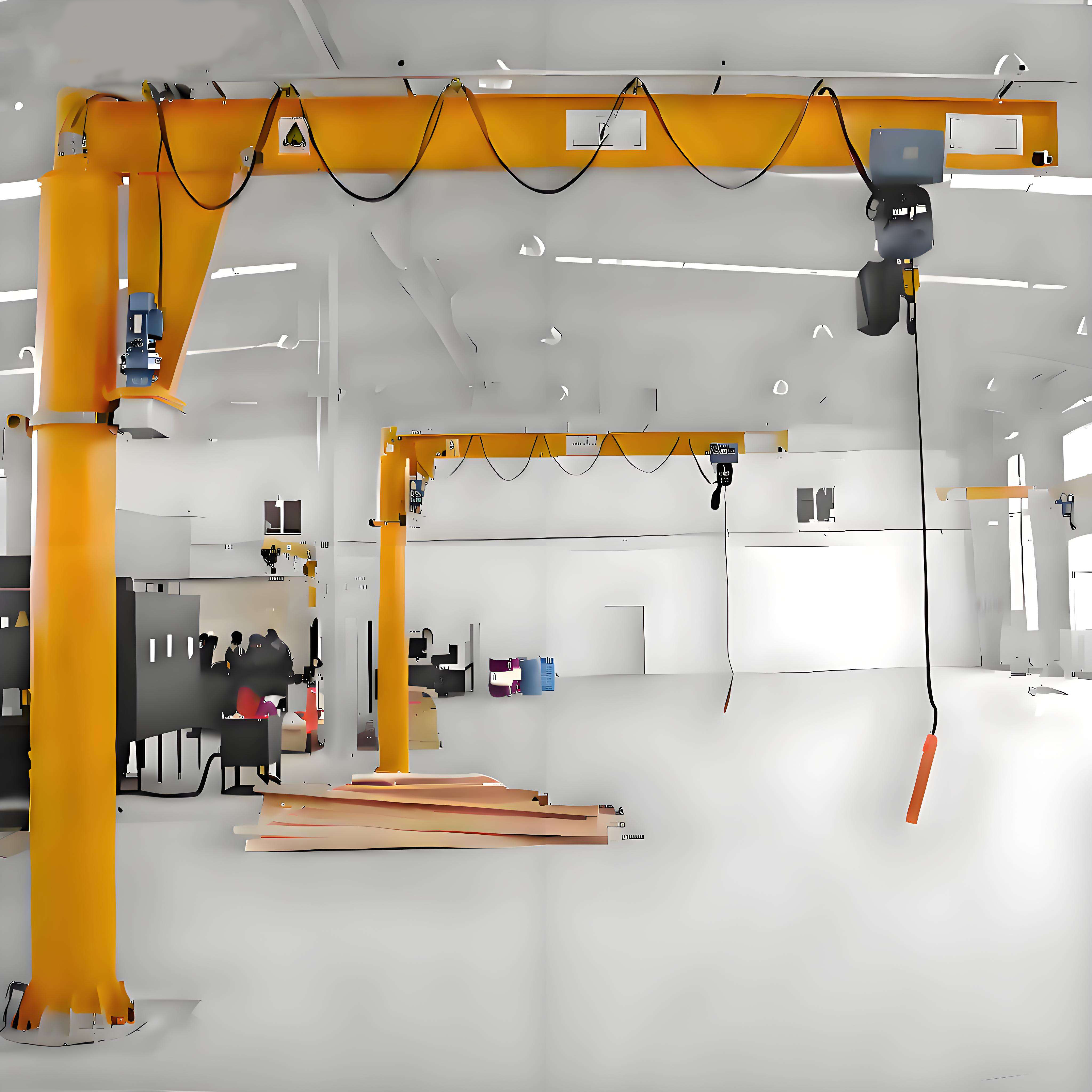
Introduction
Walk any assembly floor at the end of a long shift and you’ll see it — the operator who’s lifted the same 25-kilo casting onto the fixture two hundred times, moving slower, reaching more awkwardly, guarding a sore back. That operator isn’t lazy. They’re the predictable result of a workstation that asks a human body to do a machine’s job, cycle after cycle.
Manual handling of repetitive loads is one of the leading causes of lost-time injury in manufacturing. Back strains, shoulder tears, and pinch injuries don’t just hurt people — they show up on your books as workers’ compensation claims, replacement labor, and the quiet productivity drain of an operator working through pain. And the injuries almost always cluster around the same task: lifting, turning, and placing a heavy part at a fixed workstation, over and over.
A workstation jib crane removes the strain from that loop. It takes the weight of the part, lets the operator guide it into position with a fingertip, and returns to rest — no lifting, no twisting under load, no time pressure forcing an unsafe shortcut. The ergonomic win is obvious, but the cycle-time win often surprises buyers: when the operator isn’t fighting the weight, placement is faster and more consistent. A part that takes eight seconds to muscle into a fixture takes three to float into place on a well-positioned jib.
Here’s what makes the workstation jib different from a general-purpose crane, though — and why specifying one badly is easy. A workstation jib lives inside a tight envelope. It has to clear the machinery it serves, reach every point the operator needs without over-swinging into the next cell, cycle at production frequency without wearing out, and mount to a structure that can actually carry the forces it generates. Get any of those wrong and you’ve either bought a crane that fouls the equipment, can’t reach the fixture, fails early, or tears itself out of the wall.
This is the first article in a three-part series on jib crane procurement. Here we cover the decisions that shape a workstation jib before you compare a single price: the geometry that fits it into the cell, the reach and rotation that serve the assembly task, the column-versus-wall-mount choice and the forces behind it, the FEM/ISO duty class that determines whether it survives your production rate, and the capacity that has to include your below-hook tooling.
What you’ll take away:
- How to calculate usable hook height inside a machinery-crowded cell — and when a low-headroom hoist earns its cost
- How to size boom reach and rotation arc for a real assembly workflow, not a catalog number
- When to choose column-mounted, when to choose wall-mounted, and the structural forces each puts into your building
- How to match FEM/ISO duty class to your production frequency so the crane lasts
- Why below-hook tooling weight belongs in your capacity calculation from the start
- 2026 pricing so your budget survives the first supplier conversation
Part 1: Workstation Geometry — Fitting the Crane Into a Crowded Cell
A workstation jib rarely gets installed in open space. It goes into an assembly cell already packed with a machine, a fixture, material racks, and an operator who needs room to work. The single most common specification error is treating hook height as a simple number instead of what it really is — the leftover space after every obstruction is accounted for.
The Hook Height Calculation
Usable hook height is not the ceiling height. It’s what’s left once you subtract the hoist and account for what sits below the boom. The basic relationship:
Maximum hook height = Boom underside clearance − Hoist headroom
Where boom underside clearance is the height of the boom’s lower flange above the floor, and hoist headroom is the vertical space the hoist and trolley consume between the boom and the hook at its highest position.
Work a real example. Say the cell has a beam-mounting height of 3.2 metres, and you fit a standard electric chain hoist with 450 mm of headroom:
Maximum hook height = 3.2 − 0.45 = 2.75 metres above the floor.
Now check that against the task. The operator has to lift a part from a material rack at 0.9 metres, clear the fixture’s tallest feature at 1.4 metres, and set the part down at 1.1 metres. The lift itself only needs to move the hook between roughly 0.9 and 1.5 metres — so 2.75 metres of hook height is comfortable. But swap the standard machine for a taller one with a 1.8-metre fixture, and that margin tightens fast.
Clearance Above the Machinery
The trap is forgetting what the boom has to clear, not just the hook. In a cell built around a CNC machine, a press, or a welding fixture, the boom swings over that equipment on every rotation. If the boom’s underside sits lower than the tallest point of the machine within the rotation arc, the crane can’t complete its swing — or worse, it collides.
Before you set the mounting height, map the tallest obstruction anywhere in the boom’s rotation path: the machine enclosure, an overhead guard, a coolant line, a light fixture. The boom underside has to clear the highest of these with margin. Raising the boom to clear the machine is the obvious fix — but raising the boom eats into your hook height, and in a low-ceiling building you may not have the room. That tension is exactly where the next point comes in.
When a Low-Headroom Hoist Pays for Itself
Every millimetre of hoist headroom you save is a millimetre of hook height you gain in the same envelope. A standard chain hoist might consume 450 mm between boom and hook. A low-headroom hoist cuts that to around 250 mm — buying you 200 mm of extra usable hook height without touching the beam.
In a building with generous ceilings, that 200 mm doesn’t matter and the low-headroom premium isn’t worth it. But in a cell where the boom already has to sit high to clear the machinery, and the ceiling is tight, that 200 mm can be the difference between a crane that reaches the fixture and one that comes up short. The rule of thumb: if your hook-height calculation lands within 300 mm of what the task demands, price a low-headroom hoist before you compromise on the beam height or the lift.
Part 2: Boom Reach and Rotation Arc for Assembly Cells
Once the crane fits vertically, the next question is horizontal: does the boom reach every point the operator needs, and does it swing through the right arc to serve the workflow? This is where a jib crane either matches the cell’s real geometry or fights it.
Sizing Boom Reach to the Task
Boom reach is the horizontal distance from the mounting centre (the column or wall face) to the hook at full extension. It has to cover the full working footprint of the task — every pick point and every place point the operator uses.
Map the workflow before you pick a number. A typical assembly cell involves at least three positions: where the part arrives (a rack, a conveyor, a pallet), where it’s worked (the fixture or machine), and where it leaves (an outfeed or a finished-goods position). Measure the distance from your intended mounting point to the farthest of these, and that — plus a small margin — is your minimum reach.
Common workstation reaches run from about 2 metres for a compact cell up to 6 or 7 metres for a large one. Resist the urge to over-specify. A longer boom costs more, generates higher forces at the mount (more on that in Part 3), and — if it over-reaches the cell — can swing a suspended load into the neighbouring workstation, which is a safety problem, not a convenience.
Rotation Arc — Match the Swing to the Workflow
Reach tells you how far the hook goes; rotation arc tells you where it can go around the mount. The two mounting styles offer very different arcs, and the right one depends entirely on the cell layout.
- Full 360° rotation (available on column-mounted and free-standing jibs) lets the boom swing all the way around the mounting column. This suits a cell where pick and place points sit on opposite sides of the crane — for example, picking from a rack behind the operator and placing onto a machine in front. The column sits roughly at the centre of the working area.
- 180° rotation (typical of wall-mounted jibs) sweeps a half-circle in front of the mounting wall. This suits a cell laid out along a wall, where every working point sits within that forward arc. It uses no floor space and keeps the working zone open, but it can’t reach behind the mounting line.
There’s a subtle point buyers miss: more rotation isn’t automatically better. A 360° jib in a cell that only needs 180° can swing the load into places it shouldn’t go — into an aisle, into the next cell, into a walkway. Many workstation jibs are fitted with adjustable rotation stops precisely so you can limit the swing to the safe, useful arc. Specify the arc the workflow needs, then bound it with stops so the crane can’t travel beyond it.
Reach and Arc Together
Think of reach and arc as defining a working “pie slice” on the floor. Reach sets the radius; arc sets how much of the circle the boom sweeps. Your job in specification is to draw that slice so it covers every pick and place point the task requires — and no more. A slice that’s too small leaves the operator lifting manually at the edges; a slice that’s too big invites collisions and wasted boom cost.
Part 3: Column-Mounted vs. Wall-Mounted — Selection Logic and Structural Forces
With geometry and reach settled, the mounting decision follows — and it’s driven as much by what your building can carry as by what the workflow wants. Column-mounted (also called floor-mounted or free-standing) and wall-mounted jibs solve the same lifting problem in structurally different ways, and each pushes a different set of forces into your facility.
How Each Type Carries the Load
When a jib crane holds a load out at the end of its boom, that load creates a bending moment — a turning force that tries to rotate the crane about its base or its mounts. Everything in the mounting design exists to resist that moment. The difference between column and wall mounting is where that resistance comes from.
Column-mounted (free-standing) jib. The crane stands on its own steel column, bolted to a dedicated foundation in the floor. The column and its foundation absorb the entire bending moment. Nothing is asked of the building structure.
        Load (P)
           │
           ▼
   ┌───────────────────►  Boom (reach = R)
   │
   │  Column
   │
═══╪═══   ← Foundation
 ▲   ▲
 │   │  Foundation resists:
 │   └── Overturning moment (M = P × R)
 └────── Vertical load (P + crane weight)
The foundation sees two things: the downward vertical load, and an overturning moment equal to the load multiplied by the reach. That moment is why free-standing jib foundations are substantial — often a deep reinforced concrete block sized specifically to resist tipping. The longer the reach and the heavier the load, the bigger that foundation gets.
Wall-mounted jib. The crane bolts to a building column or a structural wall through two brackets — an upper and a lower — set a fixed vertical distance apart. Instead of a foundation resisting a moment, the two brackets resist it as a push-pull couple.
   Upper bracket ──►  TENSION (pulls off wall)
   ┌──┐
   │  │═══════════════►  Boom (reach = R)
   │  │
   │  │        Load (P)
   │  │           ▼
   └──┘
   Lower bracket ──►  COMPRESSION (pushes into wall)

   Bracket force ≈ (P × R) ÷ (vertical distance between brackets)
The load’s moment is carried by the upper bracket pulling away from the wall (tension) and the lower bracket pushing into the wall (compression). Here’s the critical part for buyers: the closer together the two brackets are, the higher those forces become, because the moment is divided by a smaller lever arm. A 1-tonne crane on a 4-metre boom can generate an upper-bracket tension force in the range of 30 to 40 kN — a serious outward pull that the wall or column absolutely must be verified to carry.
The Selection Logic
The choice usually comes down to three questions:
| Question | Points to Column-Mounted | Points to Wall-Mounted |
|---|---|---|
| Is there a suitable wall or building column at the workstation? | No — open floor, or no verified structure | Yes — a structural column or engineered wall |
| Do you need 360° rotation? | Yes — pick and place on opposite sides | No — 180° covers the workflow |
| Can you install a foundation in the floor? | Yes | No, or you want to keep the floor uninterrupted |
Choose column-mounted when you have open floor space, need full 360° coverage, and can pour a foundation. It’s self-sufficient — it imposes nothing on the building — but it costs more up front because the foundation is a real civil work, and it occupies floor space at the column base.
Choose wall-mounted when a verified structural column or wall sits right where you need the crane, 180° coverage serves the workflow, and you want to keep the floor completely clear. It’s typically cheaper (no foundation) and saves floor space — but it lives or dies on the host structure’s capacity.
The Non-Negotiable: Verify the Host Structure
The most important sentence in this entire section: before specifying a wall-mounted jib, have a structural engineer confirm the wall or column can carry the bracket forces. Those 30-to-40 kN pull forces are not something an ordinary masonry wall or a light steel column can be assumed to handle. Mounting a jib to an inadequate structure is how brackets tear loose and loads drop. If the structure can’t be verified, the answer is a column-mounted crane on its own foundation — not a hope that the wall holds.
Part 4: FEM/ISO Duty Class — Matching the Crane to Production Frequency
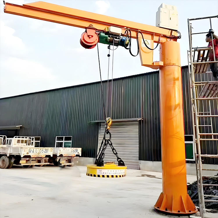
Two workstation jibs can share the same capacity, reach, and mounting, yet be built to completely different standards inside — because one is designed for occasional lifts and the other for production-rate cycling. That difference is the duty class, and it’s the specification most likely to be skipped and most likely to cause an early failure.
What Duty Class Actually Measures
Capacity tells you how heavy a single lift can be. Duty class tells you how hard and how often the crane can work over its life. The FEM (Fédération Européenne de la Manutention) and ISO classification systems combine two factors:
- Load spectrum — how heavy the average lift is relative to the rated capacity. A jib that mostly lifts light parts with the occasional heavy one lives an easier life than one running near capacity every cycle.
- Operating frequency — how many lift cycles the crane performs per hour, per shift, per day.
Together these land the crane in a group rating. The lighter groups suit intermittent, occasional service; the heavier groups suit steady, high-frequency production.
Matching Class to Your Real Production Rate
Be honest about how the workstation actually runs — not the quiet Monday, but the busy shift at full production. The questions that settle it:
- How many lift cycles per hour? A few lifts an hour is light duty. A lift every minute or two, all shift, is heavy duty.
- How close to rated capacity is the average lift? Consistently near capacity pushes the class up regardless of frequency.
- How many shifts? A single-shift cell and a three-shift cell running the same part are worlds apart on accumulated wear.
| Workstation Usage | Indicative FEM Class | Indicative ISO Group | Typical Pattern |
|---|---|---|---|
| Occasional / maintenance lifting | 1Bm | M3 | A few lifts per hour, light loads |
| Light assembly | 1Am | M4 | Regular light lifting, single shift |
| Steady production assembly | 2m | M5 | Frequent lifting through the shift |
| Heavy / multi-shift production | 3m | M6 | High-frequency cycling, near capacity |
Why This Is a Budget Decision
Under-specifying duty class is the classic false economy. A crane built for occasional service, dropped into steady production, wears through its hoist, brake, and slewing components far ahead of schedule. The failure doesn’t show on day one — it shows in month twelve, as downtime on a cell that can’t afford to stop. Over-specifying costs you too: paying for a 3m/M6 crane to do genuine 1Am/M4 work is capital spent on endurance you’ll never use.
The procurement discipline that protects you: when you compare quotes, normalise them to the same duty class. A cheaper jib at a lower duty rating isn’t the same product — it just shares a tonnage figure. That single check catches the “bargain” that would have failed inside a year.
Part 5: Capacity Specification — Don’t Forget What Hangs Below the Hook
Capacity looks like the easy number: weigh the heaviest part, pick a hoist that lifts it, done. It’s also where a surprising number of workstation jibs end up quietly under-rated — because the specification counted the part and forgot everything hanging below the hook to hold it.
Rated Capacity Is the Whole Suspended Load
The hoist doesn’t lift the part. It lifts the part plus whatever grips, supports, or positions it. In an assembly cell, that below-hook tooling is often substantial:
- Vacuum lifters for sheet, glass, or panels
- Grippers and clamps for shafts, castings, or housings
- Spreader beams and lifting frames for long or awkward parts
- Manipulators and tilting fixtures that orient the part for assembly
- Slings, shackles, and hooks in the rigging path
A below-hook manipulator or a vacuum tool can weigh tens of kilograms — sometimes over a hundred on a substantial fixture. Leave it out and your “250 kg” jib, lifting a 250 kg part on a 60 kg vacuum tool, is actually being asked for 310 kg. It’s now overloaded on the very task it was bought for.
The correct calculation is simple, and it’s the whole point:
Total suspended load = Part weight + Below-hook tooling weight + Rigging weight
Size the hoist to exceed that total with margin, then round up to the next standard capacity step (125, 250, 500 kg, 1 tonne, and so on). Standard steps keep you on catalog components — lower cost, faster delivery, easier spares — where an odd in-between figure means a custom quote and a longer wait.
Build In Working Margin
Don’t specify a hoist whose rated capacity exactly equals your total suspended load. Leave headroom. A common guideline is to work the hoist at no more than about 80% of its rated capacity in normal service — which both protects against the inevitable heavier-than-planned lift and extends component life by keeping the mechanism off its limit. If your total suspended load is 400 kg, a 500 kg hoist run at 80% gives you exactly that margin.
Account for Future Tooling
One forward-looking point worth raising at specification: assembly cells change. Today’s simple hook becomes tomorrow’s powered manipulator when the process gets upgraded. If a heavier below-hook tool is a realistic future possibility, sizing the jib and its mount to accommodate it now is far cheaper than replacing the crane later. This is a deliberate, documented decision — not blanket over-specification — but on a long-lived asset it often pays.
Part 6: 2026 Price Reference for Workstation Jib Cranes
Use these as planning figures to build a defensible budget before you approach suppliers. Actual pricing moves with capacity, reach, duty class, hoist type, and — for column-mounted units — the foundation, which is often quoted separately.
| Configuration | Capacity / Reach | 2026 Price Range (installed) |
|---|---|---|
| Wall-mounted jib, light assembly | 125–250 kg / 2–3 m | $2,000 – $5,000 |
| Wall-mounted jib, steady production | 500 kg / 3–4 m | $3,500 – $8,000 |
| Column-mounted (free-standing) jib | 500 kg / 3–4 m | $5,500 – $12,000 |
| Column-mounted, heavier production | 1 t / 4–5 m | $8,000 – $18,000 |
| Column-mounted, high-duty / long reach | 2 t / 5–6 m | $14,000 – $30,000 |
Cost drivers to build into the budget:
- Column-mounted foundation: a dedicated reinforced foundation adds real civil cost and is frequently quoted separately — confirm whether it’s in or out of a given price.
- Low-headroom hoist over a standard hoist: a modest premium, worth it only when the height envelope demands it (see Part 1).
- Higher duty class (e.g., 1Am/M4 up to 3m/M6): +15 to 40% depending on capacity, reflecting heavier-rated hoist, brake, and slewing components.
- Below-hook tooling (vacuum lifters, manipulators, custom frames): priced per application and often a significant line item in its own right — don’t fold it into a guess.
- Adjustable rotation stops and articulating booms: useful workflow options that add cost; specify them deliberately.
Procurement tip: normalise every quote to the same capacity, reach, duty class, hoist type, and — critically — the same foundation and installation scope. A wall-mounted quote sitting next to a column-mounted quote isn’t a like-for-like comparison until you’ve added the foundation to one and confirmed the host structure on the other. A headline price that looks cheaper often reflects a lower duty class or an excluded foundation, not a genuine saving.
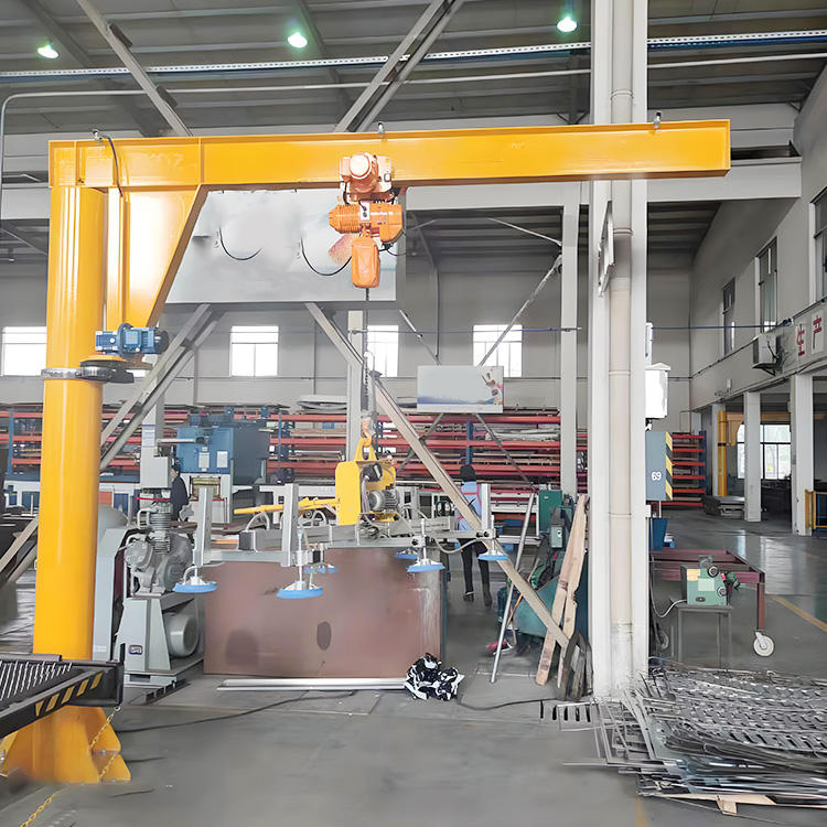
Frequently Asked Questions
Q: How do I choose between a column-mounted and a wall-mounted workstation jib crane?
A: Let your building and your workflow decide. Choose wall-mounted if a verified structural column or engineered wall sits right where you need the crane, 180° rotation covers your pick-and-place points, and you want to keep the floor clear — it’s usually cheaper because there’s no foundation. Choose column-mounted (free-standing) if you have open floor space with no suitable wall, need full 360° rotation to reach opposite sides of the cell, and can install a dedicated foundation. The decisive check for wall-mounting is structural: a 1-tonne, 4-metre jib can pull 30 to 40 kN of tension off the upper bracket, so a structural engineer must confirm the host wall or column can carry that force before you commit.
Q: Why does duty class matter more than lifting capacity for a workstation jib?
A: Capacity only tells you how heavy one lift can be; duty class tells you how hard and how often the crane can work over its life. A jib rated for 500 kg can still fail within a year if it’s a light-service crane forced into steady production — running frequent near-capacity lifts across multiple shifts. The FEM/ISO class combines load spectrum and cycle frequency to define that endurance. Match it to your busiest realistic production rate, not your average day, and if usage is uncertain, round the class up rather than down. Under-rating duty is the most common cause of early jib failure.
Q: Do I really need to include below-hook tooling in the capacity calculation?
A: Yes — always. The hoist lifts the total suspended load, which is the part plus the below-hook tooling (vacuum lifter, gripper, manipulator, spreader beam) plus the rigging. That tooling can add tens of kilograms, sometimes over a hundred. A 250 kg jib lifting a 250 kg part on a 60 kg vacuum tool is being asked for 310 kg — overloaded on its core task. Calculate total suspended load, add working margin (aim to run at around 80% of rated capacity), then round up to the next standard hoist step.
Q: When is a low-headroom hoist worth the extra cost?
A: When your hook-height calculation lands within about 300 mm of what the task needs. A low-headroom hoist consumes roughly 250 mm between boom and hook instead of the standard 450 mm, gaining you around 200 mm of usable hook height in the same envelope — equivalent to raising the beam by 200 mm without touching it. In a cell where the boom must sit high to clear machinery and the ceiling is tight, that 200 mm can be the difference between reaching the fixture and coming up short. In a high-ceiling building with room to spare, the premium isn’t worth it.
Q: How much boom reach should I specify?
A: Enough to cover every pick and place point in the task, plus a small margin — and no more. Map your workflow: where the part arrives, where it’s worked, and where it leaves. Measure from your intended mounting point to the farthest of those, and that’s your minimum reach. Over-specifying reach costs more, raises the forces at the mount, and risks swinging a suspended load into the neighbouring cell or an aisle. Where you need to bound the swing for safety, fit adjustable rotation stops so the boom can’t travel beyond the useful arc.