


Jib Crane Installation Guide: Foundation Requirements, Mounting Types, and Common Installation Mistakes
Introduction
A jib crane can be perfectly engineered and still fail — because the failure was built in during installation, not design. A foundation poured too shallow for the overturning load. An anchor bolt group torqued by feel instead of specification. A boom bolted to a column base that nobody checked against the real moment it would carry. None of these show up on day one. They surface months later as a loosening base, a boom that droops at the end of its arc, and a crane that never quite holds the load the drawings promised.
Installation is where a jib crane’s engineering either comes to life or quietly starts to unravel. And a jib crane is unforgiving in one specific way: the entire load, plus the leverage of the boom, funnels down through a single mount. There is no second support to share the burden. Get the foundation and the mounting right, and the crane runs safely for decades. Get them wrong, and the failure point is fixed from the first lift.
This guide walks through the complete jib crane installation and commissioning process from an engineering and procurement point of view. You will learn how to prepare the site, how the three main mounting types differ in their foundation and anchor requirements, why the overturning moment governs the whole foundation design, how to sequence the erection safely, how to commission the electrical system and safety devices, how to load test through the full swing arc, and the installation mistakes that cause long-term trouble. By the end, you will know what a correct jib crane installation looks like — and how to hold your installer to it.
This is article 2 of 3 in the Weiyuan Crane jib crane series. Where article 1 covered safety and OSHA compliance, this one covers how to install a jib crane so it performs for years.
Part 1: Site Preparation and Pre-Installation Checks
Everything that goes wrong later is cheaper to fix before the crane arrives. Site preparation is where you confirm the foundation, the mounting surface, and the logistics are actually ready — not assumed to be.
Confirm the Foundation or Mounting Structure
A jib crane concentrates its entire load and overturning moment at one point, so the surface it mounts to must be verified before anything is lifted:
- Floor-mounted cranes: confirm the concrete foundation is designed, poured, and fully cured to its design strength. Green concrete that has not reached strength cannot carry the anchor loads.
- Wall-mounted cranes: confirm the wall, column, or supporting steel can carry the vertical load plus the pull-out and shear forces the brackets impose. Many walls simply cannot, and this must be resolved before delivery.
- Mast-mounted cranes: confirm both the floor foundation at the base and the top support point (a roof beam or bracket) are verified for their respective reactions.
Verify Dimensions Against the Drawings
Buildings and foundations are rarely built exactly to drawing. Measure the real mounting height, the clear swing radius, the foundation dimensions, and the anchor bolt layout, then compare them against the approved crane drawings. An anchor bolt pattern that differs from the design by even a few millimetres stops the installation cold — resolve it before the boom arrives, not when the base plate will not seat.
Check the Swing Clearance
A jib crane rotates. Confirm the boom’s full swing arc is clear of machines, racking, building columns, pipework, and adjacent workstations across the entire designed rotation. Where a full 360° arc would foul an obstacle, confirm the rotation stops are set to the safe arc before installation.
Inspect Delivered Components
When the crane arrives, inspect it before installation, not after. Check the boom, column or brackets, base plate, slew bearing, hoist, trolley, control components, and anchor hardware against the packing list and drawings. Look for transit damage and confirm every bolt, clip, and anchor is present. A missing bag of anchor bolts discovered mid-installation stops the whole job.
Takeaway: Site preparation is verification, not paperwork. Confirm the foundation, the real dimensions, the swing clearance, and the delivered parts before the first lift — every gap closed here is a delay and a cost avoided later.
Part 2: The Three Mounting Types and Their Foundation Requirements
How a jib crane mounts decides everything about its foundation and anchoring. The three main types each carry the load a different way, and each demands a different foundation approach.
Type 1: Floor-Mounted (Freestanding / Column-Mounted)
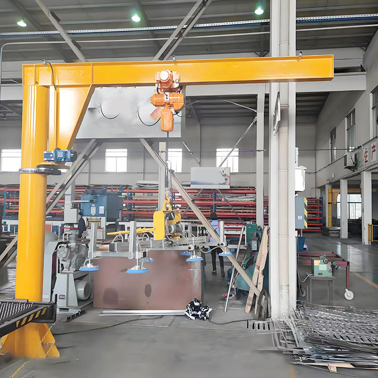
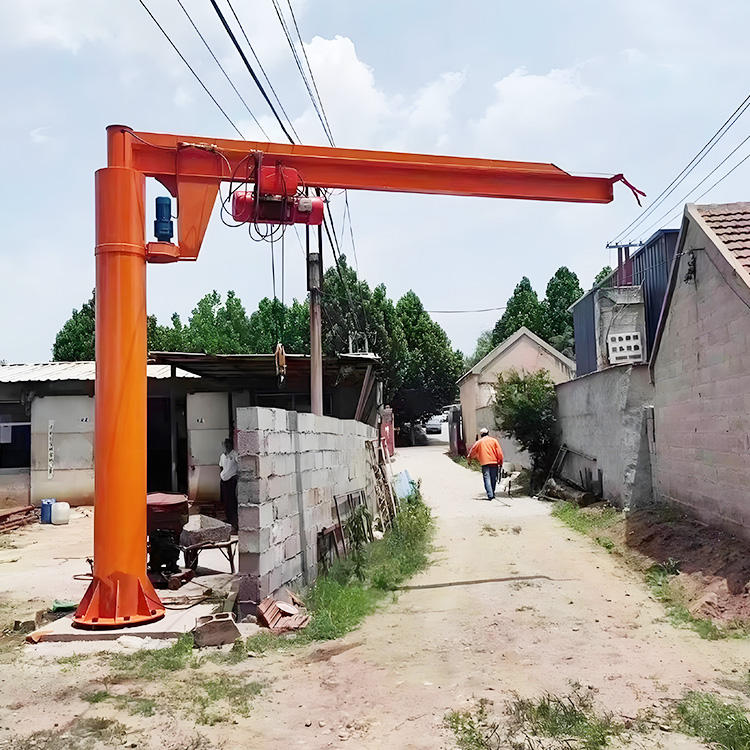
A freestanding jib crane bolts to a steel base plate anchored into a dedicated concrete foundation. The column stands alone, carrying the full vertical load and the entire overturning moment down into the foundation. This is the most common and most flexible type, needing no building support.
Foundation requirement: a reinforced concrete pad sized to resist both the downward load and the overturning moment without tipping or excessive soil pressure. The pad is typically far larger than the base plate — its size, depth, and reinforcement are driven by the overturning moment (see Part 3) and the ground bearing capacity beneath it.
Anchor requirement: high-strength anchor bolts (commonly cast-in J-bolts or a bolt cage set before the pour) sized for the tension the overturning moment produces on the far side of the base plate. The anchors must develop their full pull-out strength in the concrete, which sets the required embedment depth.
Best for: workstations where no suitable wall or column exists, and where full or near-full rotation is needed.
Type 2: Wall-Mounted (Wall Bracket or Wall Traveling)
A wall-mounted jib crane fixes its boom to brackets anchored to a building wall, column, or supporting steel. The building structure carries the load, so no floor foundation is required — but the wall now takes the full vertical load plus a substantial pull-out force at the top bracket.
Foundation requirement: none in the concrete-pad sense, but the wall or column becomes the “foundation” and must be verified for the imposed loads. The overturning moment translates into a strong outward pull on the upper anchors and a downward push on the lower ones.
Anchor requirement: the top bracket anchors carry high tension (pull-out) and must be sized and embedded accordingly — chemical anchors or through-bolts into verified structural concrete or steel, never light masonry. The connection to the building steel or reinforced concrete is the critical detail.
Best for: running a boom along a wall, saving floor space, and supplementing an overhead crane along the bay edge. Rotation is limited to roughly 180° to 200° by the wall.
Type 3: Mast-Mounted (Top and Bottom Supported)
A mast-mounted jib crane is supported at two points — a floor foundation at the base and a fixed point at the top, such as a roof beam or bracket. Because the load is shared between the top and bottom supports, the overturning moment is resolved as a horizontal force couple rather than concentrated entirely at a single base.
Foundation requirement: a floor foundation at the base carries mainly the vertical load and a horizontal reaction, so it is often smaller than a freestanding pad of the same capacity. The top support must carry an equal and opposite horizontal reaction.
Anchor requirement: base anchors sized for the vertical load and base shear; the top support connection sized for the horizontal pull. The building structure at the top point must be verified to take that force.
Best for: high lift and full 360° rotation where the building offers a solid top support, and where a smaller base foundation is an advantage.
Selection at a glance:
- No wall, full rotation, standalone → floor-mounted freestanding
- Along a wall, save floor space → wall-mounted
- Full rotation with a solid roof/beam above → mast-mounted
Takeaway: floor-mounted cranes need a large moment-resisting foundation; wall-mounted cranes transfer the load into verified building structure; mast-mounted cranes split the moment between two supports for a lighter base. The mounting type dictates the foundation before any other decision.
Part 3: Overturning Moment — Why It Governs the Foundation
The single most important number in a jib crane foundation is not the load — it is the overturning moment. Miss this and the foundation may be strong enough to hold the weight yet still tip, loosen, or crack under the leverage of the boom.
What the Overturning Moment Is
A jib crane holds its load at the end of a horizontal boom. That load, acting at a distance from the mount, creates a turning force — a moment — that tries to rotate the whole crane about the edge of its foundation or its mounting brackets. The longer the boom and the heavier the load, the larger the moment.
The core relationship is simple:
Overturning moment ≈ (Rated load + hoist/trolley weight) × boom reach + boom self-weight × its centre of gravity distance
The load’s moment dominates, and it grows directly with boom length. A 1-tonne load on a 5-metre boom produces a far larger overturning moment than the same load on a 2-metre boom — which is why boom length matters as much as capacity when sizing the foundation.
Why It Governs the Design
For a floor-mounted crane, the overturning moment does three things at once:
- It creates tension in the anchor bolts on the far side of the base plate as the crane tries to lift that edge. This sets the anchor size and embedment depth.
- It creates high bearing pressure on the near edge of the foundation as the load presses that side down. This must stay within the ground bearing capacity.
- It demands enough foundation weight and footprint to resist tipping with an adequate safety margin against overturning.
A foundation sized only for the vertical weight — ignoring the moment — will be far too small. The moment is what makes a jib crane foundation surprisingly large relative to the load it carries.
For a wall-mounted crane, the moment becomes a pull-out force on the top anchors and a push on the bottom — which is why the top bracket connection is always the critical one.
For a mast-mounted crane, the moment resolves into a horizontal force couple between the top and bottom supports, which is why its base can be smaller.
The Practical Consequence
Two jib cranes with identical capacity but different boom lengths need different foundations. Two cranes with the same capacity and reach but different mounting types need different foundations. Always size the foundation and anchors to the overturning moment at the maximum load and maximum reach, with the safety factors the applicable code requires — and have a structural engineer confirm the design.
Takeaway: the overturning moment, not the load, governs a jib crane foundation. It sets the anchor tension, the bearing pressure, and the footprint — and it grows with boom length, so reach is as important as capacity.
Part 4: Installation Sequence — Erection, Hoist, and Trolley
With the foundation cured and verified, the crane goes up. A jib crane is a sequenced, engineered lift — plumb and alignment matter far more than raw speed, because a column set out of vertical wears its slew bearing and drifts under load from day one.
Set and Level the Base
- Floor-mounted: position the base plate over the cast-in anchors or set the anchor cage, then level the plate precisely with shims or levelling nuts. Grout the base plate to the foundation once level is confirmed. The plate must be dead level so the column stands truly vertical.
- Wall-mounted: set the brackets to the marked positions and confirm they are level and correctly spaced before final anchoring.
- Mast-mounted: set the base first, then align the top support point directly above it.
Raise the Column or Boom Assembly
Plan the lift before any section leaves the ground: confirm the mobile crane or lifting method capacity, use the designed lifting points, and set an exclusion zone below. Wherever access allows, pre-assemble the column, slew bearing, and boom at ground level so the assembly goes up as one squared unit — safer and far easier to align than working piece by piece at height.
Raise the assembly and set it onto the base or brackets. As it lands:
- Confirm the column is plumb in two planes with a level — this is the single most important alignment check on a jib crane.
- Confirm the boom is horizontal across its length.
- Check the slew bearing seats correctly and the boom rotates freely through its full arc without binding.
Torque the Anchor and Structural Connections
Every anchor bolt and structural connection must be tightened to the specified torque with a calibrated wrench — not “as tight as it feels.” The anchor bolts carry the tension from the overturning moment, so an under-torqued or loose bolt group lets the base work and fatigue under every cycle. Mark each bolt as it is checked so nothing is missed. Confirm the base plate grout has cured before applying full working load.
Fit the Hoist and Trolley
Mount the trolley onto the boom and confirm it runs freely along the full length without catching. Fit the hoist, confirm it is secure, and check the wire rope or chain feeds cleanly without twist. Route the festoon cable or conductor system for the hoist so it follows the trolley and boom rotation without snagging, stretching, or fouling the swing arc.
Takeaway: erection is about plumb and alignment. Set the base dead level, confirm the column is truly vertical, torque every anchor to specification, and fit the hoist and trolley to run freely. A jib crane that goes up plumb and tight stays reliable; one set crooked wears its bearing and drifts forever.
Part 5: Electrical Connection and Safety Device Commissioning
A mechanically sound jib crane still does nothing safely until the electrical system is connected and every safety device is proven. This phase powers the crane and — just as importantly — confirms it stops safely when it must.
Connect the Power and Route the Cabling
Connect the hoist power supply and confirm the voltage and phase match the crane’s rating. Route the festoon or spiral cable so it follows the trolley travel and boom rotation cleanly — a jib crane’s rotation is the detail that most often snags or stretches poorly routed cable. Confirm the cable has slack for the full swing without dragging or pulling at the extremes of rotation.
Earthing and Bonding
Bond the crane structure, column or brackets, and any control enclosure to a common earth per the applicable electrical code, and verify continuity across every bonded point. Proper earthing protects against shock if a fault energizes the structure and keeps stray currents from disturbing the controls.
Commission the Controls
Power up and work through the commissioning sequence:
- Confirm phase rotation so all motions run in the correct direction.
- Check every motion — hoist up/down and trolley travel — against the pendant or remote labels. A reversed control is a serious hazard.
- Verify VFD settings where fitted — acceleration and deceleration ramps, speed steps, and slow-speed positioning.
Prove Every Safety Device
No jib crane is handed over until every safety device is tested and logged:
- Hoist upper limit switch: confirm it stops the hook before two-blocking, and test the backup final limit where fitted.
- Overload limiter: verify it prevents lifting beyond the set threshold.
- Emergency stop: confirm the hardwired e-stop drops all motion instantly and needs a deliberate reset.
- Rotation stops: confirm the boom’s mechanical swing stops are set and secure for the safe arc.
- Warning devices: confirm any horn, alarm, or beacon works.
Log every safety device test with a result and a date.
Takeaway: electrical commissioning is where the crane becomes safe to use, not just able to move. Route the cabling for full rotation, bond the structure, prove every motion runs the right way, and confirm every safety device — before a load ever leaves the ground.
Part 6: Load Testing Through the Full Swing Arc
Load testing is the final proof that a jib crane performs as designed. And on a jib crane, the test has one demand no bridge crane test carries: it must confirm the crane holds the load safely through its entire rotation, because the overturning moment on the mount changes as the boom swings.
Perform the Test
Before the crane enters service, load test it methodically. Per the governing standards, the test load must not exceed 125% of rated capacity unless the manufacturer specifies otherwise.
- No-load functional test first. Run the hoist and trolley through their full range and rotate the boom through its full arc unloaded, confirming smooth operation, correct limits, and brake holding.
- Rated load test. Lift the rated capacity and confirm the hoist, brake, and trolley handle it, with the brake holding the load without drift.
- Overload test to 125%. Lift the test load and confirm the boom, column, mount, and mechanisms perform without distress. Check the brake holds and inspect for any deflection.
- Rotate under load. Slew the test load through the full swing arc and confirm the mount, anchors, and foundation resist the overturning moment at every position — with special attention to the extremes of the arc where the moment on a given anchor peaks.
Verify the Mount After Testing
After the test, re-inspect the anchor bolts, the base plate or brackets, and the foundation for any sign of movement, cracking, or loosening. Confirm the anchor torque is still correct. This post-test check catches a marginal foundation before the crane goes into daily service.
Record the Result
Document the test load, the date, and the outcome, signed by the qualified person. This certified record is central to your compliance file and the baseline your maintenance program measures against.
Takeaway: a jib crane load test is not complete until the load has been carried through the full swing arc and the mount has been re-checked afterward. The rotation test is the one that proves the foundation and anchors truly resist the overturning moment.
Part 7: CMAA and ASME B30 Alignment Standards
Jib crane installation is governed by consensus standards that define both the engineering practice and the acceptance criteria. Building to them is the clearest way to demonstrate the installation was done correctly.
The Governing Standards
- ASME B30.11 covers monorails and underhung systems, including the trolley and track practice relevant to a jib crane’s boom.
- ASME B30.16 covers the overhead hoist mounted on the jib.
- CMAA classification defines the duty class the crane and its components are built to, which the installation must respect.
Where the manufacturer’s own specifications are stricter — anchor torque values, base plate levelness, boom deflection limits — follow the manufacturer, since a jib crane’s mount and slew bearing have specific requirements generic guidance does not fully cover.
Alignment Tolerances to Confirm
After erection and before load testing, confirm the installation meets the alignment criteria:
- Column plumb (verticality): the column must be vertical within the manufacturer’s tolerance in both planes. Out-of-plumb is the leading cause of uneven slew bearing wear and load drift.
- Boom level: the boom must sit horizontal across its length within tolerance.
- Trolley track: the boom track must be straight and level so the trolley runs freely without a tendency to drift to one end.
- Rotation: the boom must rotate smoothly through its full designed arc, with the swing stops set correctly.
- Base plate levelness: the base plate must be level within tolerance so the column stands plumb.
Document every alignment reading in an as-installed report and retain it. It is your compliance record and the baseline for every future check.
Takeaway: build to ASME B30.11 and B30.16 and the CMAA duty class, follow the manufacturer’s stricter tolerances, and confirm column plumb, boom level, and free rotation before load testing. Column verticality is the alignment check that matters most on a jib crane.
Part 8: Common Jib Crane Installation Mistakes
Most jib cranes that give trouble were installed with a handful of avoidable errors. These are the ones that cost facilities the most over the crane’s life.
Mistake 1: Skipping the Overturning Moment Check
The foundation is sized for the vertical load alone, ignoring the moment the boom creates. The pad is too small, the anchors carry more tension than they were designed for, and the base loosens or the foundation cracks within the first year.
Prevention: size the foundation and anchors to the overturning moment at maximum load and maximum reach, with code safety factors, and have a structural engineer confirm the design. This is the single most important jib crane foundation step.
Mistake 2: Anchor Bolts Torqued by Feel
The anchor bolts are tightened without a calibrated wrench or the specified figures. Under the cyclic tension from the overturning moment, the loose bolts work, the base plate lifts and rocks, and the mount fatigues.
Prevention: torque every anchor to the manufacturer’s specification with a calibrated wrench, mark each one, and re-check after the first weeks of service and after load testing.
Mistake 3: Rigidly Welding a Trolley Rail Instead of Correct Anchoring
On boom or track sections, the rail is welded solid where it should be clamped, leaving no allowance for thermal movement and locking in stress. Over seasons of cycling, the rail distorts and the trolley begins to catch.
Prevention: anchor trolley rails with the specified clip or connection system that holds them securely while allowing thermal movement — never a rigid weld where the design calls for a clamped joint.
Mistake 4: Setting the Column Out of Plumb
The column is bolted down without confirming it is truly vertical. The crane drifts under load, the boom tends to swing back to one position on its own, and the slew bearing wears unevenly from the first shift.
Prevention: level the base plate precisely and confirm column plumb in two planes before finalizing the anchors. Correct any out-of-plumb before grouting and full tightening.
Mistake 5: Commissioning Before Testing Safety Devices
The crane is released because it moves, before the upper limit, overload limiter, e-stop, and rotation stops are proven. The protection is missing exactly when it is first needed.
Prevention: test and log every safety device during commissioning, and hand over no crane until each one is proven to work.
Mistake 6: Load Testing Without Rotating the Boom
The crane is tested at a single boom position, so the mount is never proven under the changing moment through its full arc. A weak anchor or marginal foundation on one side goes undetected until it fails in service.
Prevention: slew the test load through the full swing arc and re-inspect the mount and anchors afterward.
Mistake 7: Accepting Handover Without Documentation
The crane is put to work with no foundation record, alignment survey, or load test certificate. When a problem appears later, there is no baseline to diagnose against and no proof the installation was compliant.
Prevention: insist on a complete, signed handover pack — foundation and anchor records, alignment survey, commissioning log, and load test certificate — before accepting the crane.
Takeaway: almost every long-term jib crane problem traces back to a skipped moment check, an untorqued anchor, an out-of-plumb column, an untested safety device, or a single-position load test. Close those gaps and you close most of your future trouble.
Frequently Asked Questions
Q: What kind of foundation does a floor-mounted jib crane need?
A freestanding floor-mounted jib crane needs a reinforced concrete foundation sized to resist both the vertical load and the overturning moment the boom creates. Because the moment tries to tip the crane and pull up the far anchor bolts, the foundation is usually far larger than the base plate — its size, depth, and reinforcement are driven by the overturning moment at maximum load and reach, and by the ground bearing capacity beneath it. A structural engineer should confirm the design, and the concrete must reach its design strength before the crane carries any load.
Q: Why does the overturning moment matter more than the load for a jib crane foundation?
Because a jib crane holds its load at the end of a boom, the load acts at a distance from the mount and creates a turning force that tries to rotate the crane about its foundation edge. This moment — not the vertical weight — sets the anchor bolt tension, the foundation bearing pressure, and the footprint needed to resist tipping. A foundation sized only for the weight will be far too small. The moment grows directly with boom length, so a longer reach needs a bigger foundation for the same capacity.
Q: What are the three main jib crane mounting types?
The three main types are floor-mounted (freestanding or column-mounted, bolted to a dedicated concrete foundation and carrying the full moment down into it), wall-mounted (fixed to brackets on a building wall or column, which then carries the load with high pull-out force on the top anchors), and mast-mounted (supported at both a floor base and a top point, splitting the overturning moment into a horizontal force couple so the base foundation can be smaller). The choice depends on rotation needs, available building structure, and floor space.
Q: How much rotation does each mounting type allow?
A floor-mounted freestanding jib crane typically allows full or near-full 360° rotation. A wall-mounted crane is limited by the wall to roughly 180° to 200°. A mast-mounted crane, supported top and bottom, generally allows full 360° rotation. Confirm the swing arc is clear of obstructions across the full designed rotation during site preparation, and set the mechanical rotation stops for the safe arc before commissioning.
Q: Why must a jib crane be load tested through its full swing arc?
Because the overturning moment on the mount and anchors changes as the boom rotates. Testing at a single position proves only that one loading condition, leaving a weak anchor or marginal foundation on another side undetected. Slewing the test load through the full arc confirms the mount, anchors, and foundation resist the moment at every position, with the extremes of the arc often the most demanding. Re-inspecting the anchors and base after the test catches any movement before the crane enters daily service.
Q: What alignment tolerance matters most when installing a jib crane?
Column plumb — the verticality of the column — is the most important. An out-of-plumb column makes the crane drift under load, causes the boom to swing back to one position on its own, and wears the slew bearing unevenly from the first shift. Level the base plate precisely and confirm the column is vertical in two planes before finalizing the anchors. The boom must also be horizontal and the trolley track straight and level so the trolley runs freely.
Q: Can a jib crane be mounted to any building wall or column?
No. A wall-mounted jib crane imposes the full vertical load plus a substantial pull-out force on the upper anchors from the overturning moment, and only verified structural concrete or steel can carry it — never light masonry or an unverified wall. The wall or column becomes the crane’s “foundation” and must be assessed for the imposed loads before installation. Where the structure cannot take the forces, a freestanding floor-mounted crane on its own foundation is the safer choice.
Q: What standards govern jib crane installation?
Jib crane installation is guided by the ASME B30 series — chiefly B30.11 for underhung and monorail practice relevant to the boom and trolley, and B30.16 for the overhead hoist — along with the CMAA duty classification that defines how hard the crane and its components are built to work. The manufacturer’s own specifications for anchor torque, base plate levelness, column plumb, and boom deflection are essential and often stricter, since a jib crane’s mount and slew bearing have specific requirements generic guidance does not fully cover.