


KBK Crane System Design and Installation Guide: Track Layout, Suspension, and Commissioning
Introduction
A KBK crane system rarely fails because a part was weak. It fails because the layout was planned around a drawing instead of the work, the suspension was spaced too far apart, or the building could not carry what someone assumed it could. None of these show up on the first lift. They surface weeks later as a track that sags at midspan, a trolley that stalls in a low spot, or a suspension bracket working loose under a roof beam that was never checked.
For plant engineers and procurement managers, the value of a KBK system lives in getting the design and installation right. The components are standardized and forgiving. The layout, the suspension spacing, and the structural verification are where a good system separates from a troublesome one. Plan those well and the crane pushes by hand, tracks smoothly, and reconfigures with the line for years. Plan them poorly and you fight deflection, binding, and rework from day one.
This guide is article 2 of 3 in the Weiyuan Crane KBK series. Article 1 covered what a KBK system is and how it works. This one covers how to design and install it. Here is what you will learn:
- How to plan the right layout — monorail, single-girder, or grid — and map coverage
- How to select track profiles and engineer suspension spacing for the load and span
- How to verify the building structure and when to specify a freestanding frame
- The step-by-step installation sequence, from suspension to hoist
- How to connect and commission the electrical system, then load test and align the crane
- The common design and installation mistakes that cause long-term trouble
Part 1: Planning Your KBK Layout
Every KBK project starts with one question: where does the lifting actually happen, and how far does it need to reach? Answer that honestly and the layout almost designs itself. Guess at it, and you build coverage you do not use or leave gaps you cannot lift into.
Map the Coverage First
Before choosing any component, walk the floor and mark where loads are picked up and set down. Note the machines, benches, and stations the crane must serve, and the paths loads travel between them. This coverage map — not a catalog layout — drives the whole design.
Ask three questions at each point:
- What is the heaviest load lifted here?
- How often is it lifted?
- Does the load stay at one spot, move along a line, or move across an area?
The answers sort you toward one of the three standard layouts.
The Three Standard Layouts
Monorail. A single track profile along which a trolley and hoist travel in a straight line. It is the simplest, lowest-cost KBK layout, ideal for feeding one machine, moving parts along a bench, or transferring loads between two fixed points. If the work follows a line, a monorail fits.
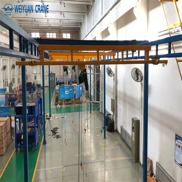
Single-girder suspension crane. A bridge track runs across two parallel runway tracks, so the hoist reaches any point within a rectangle. This is workstation-area coverage without the weight and cost of a full overhead crane. If the work covers a defined rectangular zone, choose a single-girder layout.
Grid (multi-bridge) system. Several bridges, runways, and switches combine to cover a large floor or transfer loads between zones. Grids suit assembly lines and large cells where lifting must reach everywhere. If the work spans a big area or moves between bays, a grid earns its complexity.
Respect the Span Limits
Span is where good layouts go wrong. Every track profile has a practical unsupported span — the distance it can bridge between supports or between a bridge’s two runway connections before deflection becomes a problem. Push past it and the track sags, the trolley labors through the low point, and hand-pushed movement stops being effortless.
For runway and bridge tracks, size the span to the profile and the load, not to a convenient column spacing. Where the required span exceeds a single profile’s limit, add an intermediate support, step up to a heavier profile, or accept a shorter bridge. Never stretch a profile to fit a layout it was not sized for.
Takeaway: Plan the layout from a real coverage map, not a catalog. Monorail for a line, single-girder for a zone, grid for a whole floor — and always keep spans inside the profile’s practical limit.
Part 2: Track Profile Selection and Suspension Spacing
With the layout chosen, the next decisions set how the system carries load and how smoothly it runs: the track profile and the spacing of its suspension points.
Choosing the Track Profile
KBK track profiles come in two materials, and the choice shapes both capacity and ergonomics.
Steel profiles are cold-rolled enclosed sections offering higher capacity and longer unsupported spans. They are the standard for heavier KBK loads, longer runways, and wider bridges. Where the load climbs toward the top of the KBK range or the span is long, steel is the answer.
Aluminum profiles are lightweight extruded sections with very low rolling resistance. They suit ergonomic, hand-pushed lifting where an operator moves the load by hand all shift. The low friction is the point — it turns repetitive positioning into an effortless push. Where the work is manual and repetitive at lighter loads, aluminum wins.
Match the profile to three things at once: the load, the span it must bridge, and how the load moves. A short monorail with light, hand-pushed parts calls for aluminum; a long steel runway carrying near-maximum load calls for a heavier steel section.
Engineering the Suspension Spacing
Suspension spacing — the distance between the brackets that hang the track from the structure — is the single most important number in a KBK design after the profile itself. It controls deflection, and deflection controls how the crane runs.
The rule is direct: the heavier the load and the lighter the profile, the closer the suspension points must sit. A track hung with brackets spaced too far apart sags between them, creating a shallow valley the trolley must climb out of on every pass. That valley wears the trolley wheels, tires the operator, and, over time, fatigues the track.
Three factors set the spacing:
- Load. Heavier loads demand closer suspension.
- Profile. A stiffer, heavier profile spans farther between supports than a light one.
- Layout position. Runway tracks, which carry the bridge and its load, are typically suspended more closely than a lightly loaded monorail.
Always size suspension spacing to the profile manufacturer’s load-span data for your actual load, and confirm the resulting deflection stays within tolerance. Do not space brackets to match roof purlins for convenience — space them to control deflection, then find a way to anchor them to the structure.
Suspension Types
The suspension brackets themselves come in rigid and articulating forms. Rigid hangers hold the track firmly in position, while articulating hangers allow slight movement to accommodate building deflection or thermal effects. On longer runs, a mix keeps the track properly located without locking in stress as the building moves.
Takeaway: Choose steel for capacity and span, aluminum for ergonomics — and set suspension spacing from real load-span data, not from where the roof steel happens to sit.
Part 3: Building Structure Verification and Freestanding Frames
A KBK system is light, but it is not weightless. Every suspension point pushes and pulls on the structure above it, and that structure must be verified before anything is hung from it. Skip this step and you learn its importance when a bracket starts to distort a roof purlin.
Verify the Supporting Structure
The building elements that carry a KBK system — roof beams, purlins, or existing steelwork — must be confirmed to take the crane’s dead weight plus the rated load plus the dynamic forces of lifting and travel, delivered at each suspension point. This is a real structural check, not an assumption.
Two points deserve attention:
- Loads are concentrated at the suspension points, not spread evenly. Each bracket delivers a point load into the structure. A roof designed for a uniform distributed load may not accept concentrated hangers without reinforcement.
- Uplift and lateral forces exist too. Lifting and travel apply more than a simple downward pull. The connection to the structure must resist the full set of forces, not just the static weight.
Where the existing structure can carry the loads, hang the system directly. Where it cannot — or where the check is inconclusive — you have two choices: reinforce the structure, or decouple the crane from the building with a freestanding frame.
Freestanding Support Frames
A freestanding frame carries the KBK system on its own columns and headers, transferring the load to the floor and its foundations rather than the building. It is the right choice when:
- The roof or existing steel cannot carry the crane and reinforcement is impractical.
- The building is leased or the layout must stay independent of the structure.
- The system may be relocated, and a self-supporting frame moves with it.
- Precise suspension spacing is needed that the building’s grid cannot provide.
The frame’s columns need their own foundations, sized for the vertical load and any moment the layout imposes. This adds cost over roof suspension, but it buys independence from the building and full freedom over where the suspension points sit — which often makes for a better-running crane.
Takeaway: Verify the structure at every suspension point before hanging anything. Where it cannot carry the concentrated loads, reinforce it or specify a freestanding frame that stands on its own foundations.
Part 4: Step-by-Step Installation Sequence
With the layout designed, the profiles chosen, and the structure verified, installation follows a clear sequence. Work it in order — each step sets up the one after it, and skipping ahead builds error into the system.
Step 1: Set Out and Install the Suspension
Start from the top. Mark the suspension point positions from the design layout, confirming the spacing matches the engineered figures, not a rough approximation. Install the suspension brackets to the verified structure or freestanding frame, and set them to the correct height and line.
Getting the suspension right is the foundation of a smooth-running system. If the hangers are off in height, the track will run uphill and downhill; if they are off in line, the track will curve where it should be straight. Level and align the brackets before any track goes up.
Step 2: Join the Track Sections
Lift the track profiles into the suspension brackets and bolt the sections together end to end with the standard connectors. As each joint is made:
- Confirm the running surfaces align. The inside of the enclosed profile must be continuous and flush across the joint so the trolley rolls through without catching.
- Check the track is level and straight. Survey along the run and correct any high or low bracket before moving on.
- Torque the connector bolts to specification. A loose joint works under travel and eventually steps out of line.
For bridge and runway layouts, join the runway tracks first, confirm they are parallel and level, then fit the bridge track across them.
Step 3: Fit the Trolleys
Insert the trolleys into the enclosed track profile at the designated end and confirm they run freely along the full length. Push each trolley by hand through the whole run and feel for binding, stiff spots, or steps at the joints. A trolley that stalls anywhere signals a misaligned joint or a suspension height error — fix it now, before the hoist adds weight.
Fit the end stops at each track end to limit trolley travel safely.
Step 4: Mount the Hoist
Mount the hoist to its trolley and confirm it is secure. Check the wire rope or chain feeds cleanly without twist, and that the hoist hangs square. On a bridge layout, confirm the bridge trolley carries the hoist across the full bridge length without catching, and that the whole bridge traverses the runways freely.
With the hoist mounted, push the loaded assembly through its full range of motion — trolley along the bridge, bridge along the runways — and confirm smooth, effortless travel everywhere.
Takeaway: Install top-down and in order — suspension, then track, then trolleys, then hoist. Confirm free hand movement at every stage, because a problem caught before the next step is a fraction of the cost to fix.
Part 5: Electrical Connection and Commissioning
A KBK system moves by hand at the trolley, but the hoist and any powered travel still need a correctly connected and commissioned electrical supply. This phase powers the lift and proves it stops safely.
Connect the Power Supply
Connect the hoist power supply — typically a festoon cable system running along the track — and confirm the supply voltage and phase match the hoist rating. Route the festoon so it follows the trolley and bridge travel cleanly, with enough slack to reach the full extent of movement without dragging, stretching, or snagging at the ends of travel.
On a bridge or grid layout, confirm the cabling accommodates both the trolley traveling along the bridge and the bridge traveling along the runways — the point where poorly routed cable most often binds.
Earth and Bond the System
Bond the track, the suspension or frame, and any control enclosure to a common earth per the applicable electrical code, and verify continuity across every bonded point. Proper earthing protects against shock if a fault energizes the structure and keeps stray currents from disturbing the controls.
Commission the Hoist and Controls
Power up and work through the commissioning sequence:
- Confirm phase rotation so all powered motions run in the correct direction.
- Check every motion — hoist up and down, and any powered travel — against the pendant or remote labels. A reversed control is a serious hazard.
- Verify the hoist upper limit switch stops the hook before two-blocking, and test any backup final limit.
- Test the overload device where fitted, confirming it prevents lifting beyond the set threshold.
- Confirm the emergency stop drops all motion instantly and requires a deliberate reset.
Log every safety device test with a result and a date. No KBK system should be handed over until each device is proven to work.
Takeaway: Route the festoon for full travel, bond the system to earth, and prove every motion and safety device before a load leaves the ground.
Part 6: Load Testing and Alignment Tolerances
Load testing is the final proof that the system performs as designed and is safe to release into service. Alignment confirms it will run smoothly for years.
Perform the Load Test
Before the system enters service, load test it methodically. The test load should not exceed 125% of the rated capacity unless the manufacturer specifies otherwise.
- No-load functional test first. Move the trolley and bridge through their full range unloaded, confirming smooth travel, correct limits, and the hoist brake holding.
- Rated load test. Lift the rated capacity and confirm the hoist and brake handle it, with the brake holding the load without drift.
- Overload test to 125%. Lift the test load and confirm the track, suspension, connectors, and hoist perform without distress. Inspect the track for deflection and the suspension points for any movement.
- Move under load. Push the test load through the full travel range and confirm the trolley runs smoothly at every point, with no low spots or binding.
Inspect the Suspension After Testing
After the test, re-inspect the suspension brackets, connectors, and the structure or frame for any sign of movement, distortion, or loosening. Confirm the connector and bracket bolts are still correctly torqued. This post-test check catches a marginal suspension point before the system goes into daily service.
Confirm the Alignment Tolerances
A KBK system runs well only when the track is straight, level, and continuous. After installation and before handover, confirm:
- Track straightness: each runway and bridge track runs true, with no lateral curve that would drag the trolley to one side.
- Track level: the track is level along its length so the trolley does not run uphill or roll away downhill in a low spot.
- Runway parallelism: on bridge layouts, the two runway tracks are parallel within tolerance so the bridge travels squarely without skewing.
- Joint continuity: the running surface is flush and stepless across every connector, so the trolley rolls through without a bump.
Document every reading in an as-installed report and retain it as the baseline for future checks.
Takeaway: Load test to 125%, move the load through the full range, re-inspect the suspension afterward, and confirm the track is straight, level, parallel, and stepless before handover.
Part 7: Common Design and Installation Mistakes
Most KBK systems that give trouble were let down by a handful of avoidable errors. Knowing them upfront is the cheapest protection you can buy.
Mistake 1: Over-Spanning the Track
The track is stretched too far between suspension points to save on brackets or match the roof grid. It sags at midspan, the trolley labors through the low spot, and hand-pushed movement stops being effortless.
Prevention: Set suspension spacing from the profile’s load-span data for your actual load, and confirm deflection stays in tolerance. Add supports rather than stretch a profile past its limit.
Mistake 2: Skipping the Structural Check
The system is hung from a roof or existing steel that nobody verified for the concentrated point loads. The structure distorts, the suspension loosens, and the track drifts out of line.
Prevention: Verify the structure at every suspension point for the full vertical, uplift, and lateral loads. Where it cannot carry them, reinforce it or specify a freestanding frame.
Mistake 3: Misaligning the Track Joints
Track sections are bolted together without confirming the running surfaces are flush and continuous. The trolley catches at every joint, wearing its wheels and jolting the load.
Prevention: Confirm each joint is flush and stepless, the track is straight and level, and the connector bolts are torqued to specification before fitting the trolleys.
Mistake 4: Choosing the Wrong Profile Material
A heavy steel profile is used where an aluminum one would let operators push loads by hand, wasting the system’s biggest advantage — or an aluminum profile is stretched over a span that only steel could carry.
Prevention: Match the profile to the load, the span, and how the load moves. Aluminum for ergonomic hand-pushed lifting; steel for higher capacity and longer spans.
Mistake 5: Poorly Routed Festoon Cable
The festoon is routed without enough slack for the full travel, so it drags, stretches, or snags at the extremes of trolley and bridge movement — especially on grid layouts.
Prevention: Route the festoon to follow every powered motion with adequate slack, and test it through the full travel range during commissioning.
Mistake 6: Commissioning Before Testing Safety Devices
The system is released because it lifts and moves, before the upper limit, overload device, and e-stop are proven. The protection is missing exactly when it is first needed.
Prevention: Test and log every safety device during commissioning, and hand over no system until each one is proven.
Mistake 7: No As-Installed Documentation
The system goes to work with no suspension record, alignment survey, or load test certificate. When a problem appears later, there is no baseline to diagnose against.
Prevention: Insist on a complete, signed handover pack — suspension and structural records, alignment survey, commissioning log, and load test certificate — before accepting the system.
Takeaway: Almost every long-term KBK problem traces back to over-spanning, an unchecked structure, a misaligned joint, or an untested safety device. Close those gaps and you close most of your future trouble.
Frequently Asked Questions
Q: How do I choose between a monorail, single-girder, and grid KBK layout?
Start with how the work flows. A monorail suits lifting that follows a straight line — feeding one machine or moving parts along a bench. A single-girder suspension crane, with a bridge running across two runways, covers a rectangular zone for workstation-area lifting. A grid of multiple bridges and switches covers a large floor or transfers loads between zones. Map where loads are picked up and set down first, then match the layout to that coverage rather than to a catalog example.
Q: How far apart should KBK suspension points be?
Suspension spacing depends on the load, the track profile, and the layout position, and it must come from the profile manufacturer’s load-span data for your actual load. Heavier loads and lighter profiles need closer spacing; stiffer steel profiles span farther than aluminum ones; and runway tracks carrying a bridge are usually suspended more closely than a lightly loaded monorail. Space the brackets to control deflection within tolerance — never stretch them to match the roof grid for convenience.
Q: What is the difference between aluminum and steel KBK track profiles?
Steel profiles offer higher capacity and longer unsupported spans, making them the choice for heavier loads and longer runways or bridges. Aluminum profiles are lighter with very low rolling resistance, ideal for ergonomic, hand-pushed lifting where operators move loads by hand throughout a shift. Choose based on your load, the span the track must bridge, and how much manual movement the work involves — aluminum for effortless positioning at lighter loads, steel for capacity and span.
Q: Do I need to reinforce my building for a KBK system?
It depends on the structure. A KBK system delivers concentrated point loads into the roof beams, purlins, or existing steel at each suspension bracket, plus uplift and lateral forces from lifting and travel. A roof designed only for a uniform distributed load may not accept these without reinforcement. Verify the structure at every suspension point before installation. Where it cannot carry the loads, either reinforce it or specify a freestanding support frame that stands on its own foundations.
Q: When should I choose a freestanding frame instead of roof suspension?
Choose a freestanding frame when the roof or existing steel cannot carry the crane and reinforcement is impractical, when the building is leased or the layout must stay independent of the structure, when the system may be relocated later, or when you need precise suspension spacing the building grid cannot provide. The frame carries the system on its own columns and foundations, adding cost but buying independence from the building and full freedom over where the suspension points sit.
Q: How is a KBK system load tested?
Load test before the system enters service, with a test load not exceeding 125% of rated capacity unless the manufacturer specifies otherwise. Run a no-load functional test first, then lift the rated load and confirm the brake holds without drift, then lift the 125% test load and inspect the track, suspension, and connectors for distress. Move the test load through the full travel range to confirm smooth trolley movement everywhere, and re-inspect the suspension points afterward. Record the result, dated and signed, as a compliance and maintenance baseline.
Q: What alignment tolerances should a KBK system meet?
The track must be straight so the trolley does not drag to one side, level so it does not run uphill or roll away in a low spot, and continuous with flush, stepless joints so the trolley rolls through each connector without a bump. On bridge layouts, the two runway tracks must be parallel within tolerance so the bridge travels squarely without skewing. Confirm all of these after installation and before handover, and document the readings as your as-installed baseline.
Q: Can a KBK system be extended or relocated after installation?
Yes — the bolted, modular construction is designed for it. Track sections, bridges, and stations can be added, shortened, or moved as your production layout changes, reusing the same standardized components rather than scrapping a fixed crane. When you extend or relocate, re-verify the suspension spacing and the supporting structure for the new configuration, and re-run the alignment checks and a load test before returning the system to service.