


KBK Freestanding vs. Suspended Crane Selection Guide: Structural Constraints, Space Optimization & Installation Standards
Introduction
In modern light-material handling, KBK flexible modular crane systems have become the industry standard across automotive, electronics assembly, and machinery manufacturing sectors—thanks to their modular design, low motion resistance, and versatile expandability. However, during early facility planning, engineering teams often hesitate between Suspended KBK (KBK-S) and Freestanding KBK (KBK-F) systems.
Making the wrong choice can lead to skyrocketing installation costs, structural safety hazards due to insufficient building roof capacity, or unnecessary floor obstructions caused by excessive support columns.
This guide addresses the core pain points identified across hundreds of site surveys by Chengdu Weiyuan engineers. It provides a structured breakdown of geometry, roof/floor loading requirements, headroom calculations, and selection criteria to help you specify the optimal workstation crane layout.
Part 1: Matching Building Structure with KBK Configurations
1. Structural Requirements for Suspended KBK (KBK-S)
Suspended KBK cranes attach directly to existing roof trusses, I-beams, or concrete ceiling structures, offering the primary advantage of zero floor space footprint.
- Vertical & Dynamic Shear Forces: Suspension points must withstand the total deadweight, rated lifting capacity, dynamic shock factors (typically $1.25\times$), and lateral forces generated by trolley motion.
- Roof Truss & Concrete Beam Evaluation: Steel structures require verification of lower-chord node strength. Concrete ceiling installations require high-strength chemical anchors or through-bolt backing plates.
- Support Spacing Limits: Standard KBK track spans typically range from 3 to 8 meters. For facilities with wider column spacing (e.g., over 12 meters), secondary longitudinal support beams must be installed.
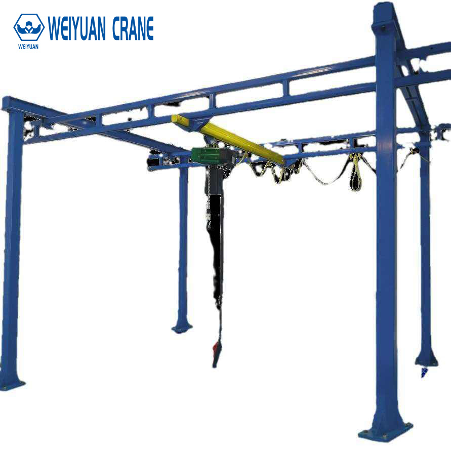
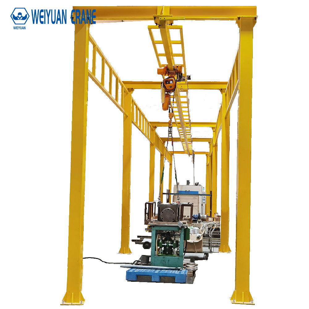
2. Space and Foundation Requirements for Freestanding KBK (KBK-F)
When the building roof cannot support additional loads (such as light steel sheet roofs, insulated sandwich panels, or aged structures), Freestanding KBK is the mandatory solution.
- Concrete Floor Requirements: Freestanding columns rely on floor anchor baseplates. Recommended minimum concrete floor thickness is $\ge 150\text{ mm}$ with a compressive strength class of at least C25.
- Column Placement & Safety Clearance: Support columns occupy valuable floor area. Layout designs must avoid main forklifts pathways, aisleways, and equipment maintenance access zones. A safety clearance of $\ge 500\text{ mm}$ between column edges and traffic lanes is recommended.
Part 2: Track Selection & Headroom Calculation
1. Maximum Hook Height (Headroom) Formula
In facilities with limited ceiling height, available headroom dictates vertical lifting range:
$$\text{Maximum Hook Height} = \text{Effective Ceiling Height} – (\text{Main Girder Track Height} + \text{Suspension Hardware Height} + \text{Hoist Body Height})$$
- Standard KBK: The electric chain hoist hangs beneath the main bridge girder, running along the lower flange or internal track profile.
- Low-Headroom KBK Solutions: Utilizing raised bridge designs or nesting the hoist between double girders saves $200\text{ to }400\text{ mm}$ of vertical space—ideal for low-clearance warehousing.
2. Track Material Comparison: Steel vs. Aluminum KBK
| Dimension | Steel KBK Track (KBK-II / KBK-III) | Aluminum KBK Track (Aluminium) |
|---|---|---|
| Weight & Push/Pull Resistance | Higher deadweight; manual push resistance $\approx 1\% \text{ to } 1.5\%$ of load | $\sim 40\%$ lighter; push resistance $< 0.5\%$ of load |
| Max Single-Girder Span | Medium span capability (up to 2,000 kg capacity) | Low deflection on long bridges; effortless manual travel |
| Cleanliness & Corrosion | Requires protective coating; standard shop floor use | Zero paint-flaking; rust-proof; suitable for cleanrooms |
Part 3: Load Calculations & Safety Margins
When specifying the rated capacity of a KBK crane system, never calculate based solely on the net weight of the payload.
Total Design Load Formula:
$$\text{Total Design Load} = (\text{Max Workpiece Weight} + \text{Rigging/Gripper Weight} + \text{Hoist Deadweight}) \times \text{Dynamic Impact Factor }(1.2)$$
Example: Lifting a $500\text{ kg}$ engine block using a $35\text{ kg}$ custom gripper and a $45\text{ kg}$ electric chain hoist:
$$\text{Total Design Load} = (500 + 35 + 45) \times 1.2 = 696\text{ kg}$$
In this scenario, a 1,000 kg (1-Ton) rated KBK system must be specified. Selecting a 500 kg system would lead to permanent track deformation under dynamic loading.
Part 4: 2026 Price Reference Guide
Prices below include standard steel track, suspension components, manual/electric trolleys, and an electric chain hoist (average industrial spec, excluding freight and site civil works):
- Suspended Single-Girder KBK (500 kg, 4m Bridge, 10m Runway): $2,100 to $3,900
- Freestanding Double-Girder KBK (1,000 kg, 6m Bridge, 12m Runway): $4,900 to $9,100
- High-End Aluminum KBK System (500 kg, Cleanroom Spec, 5m Bridge, 10m Runway): $6,300 to $11,200
Frequently Asked Questions (FAQ)
Q: Can we install a suspended KBK crane directly onto a space-frame (grid) roof structure?
A: Space-frame structures are designed primarily for uniform static loads and are sensitive to concentrated point loads and dynamic side-thrusts. Structural verification by the original building designer or Chengdu Weiyuan engineers is required. Specialized spherical node clamps or load-distributing sub-frames are usually mandatory.
Q: How difficult is it to extend or reconfigure a KBK track system in the future?
A: Modular design is the core advantage of KBK systems. All track sections use standardized bolted connections. System extensions, track relocations, or layout modifications can be executed quickly with over 90% component reusability.