


Overhead Crane Runway Design Guide: Rail, Span, and Building Structure Requirements
Introduction
A crane gets all the attention at purchase, but the runway it rides on decides whether that crane runs sweetly or fights you for the next 30 years. Nobody photographs a runway beam. Nobody brags about their rail anchoring. Yet a runway set 4mm out of level, a beam that deflects too far under load, or a column that was never checked for the crane’s wheel loads will quietly wear out flanges, crack welds, and turn a good crane into a maintenance headache.
The runway is the foundation of an overhead crane system. It carries every load the crane lifts, guides the crane’s travel, and transfers the whole assembly’s forces into your building. Get it right and the crane tracks straight, wears evenly, and needs little more than routine attention. Get it wrong and you inherit skew, vibration, uneven wheel wear, and structural fatigue that no amount of crane maintenance can fix — because the fault is in the runway, not the crane.
This guide walks through overhead crane runway design from a plant engineer’s and procurement manager’s point of view. You will learn how a runway system is put together, how to select runway beams and rails, the CMAA and ASME B30.2 alignment tolerances that govern the whole design, how span and deflection interact, what the crane demands of your columns and foundations, how to anchor the rail correctly, how to specify end stops and bumpers, and the runway design mistakes that cost facilities the most. By the end, you will know what a sound runway design looks like — and how to hold your supplier and installer to it.
This is article 2 of 3 in the Weiyuan Crane overhead crane internal linking series. Where article 1 covered overhead crane types and applications, this one covers the runway that carries them.
What a Runway System Actually Is
Before designing anything, it helps to see the whole system and how its parts share the load.
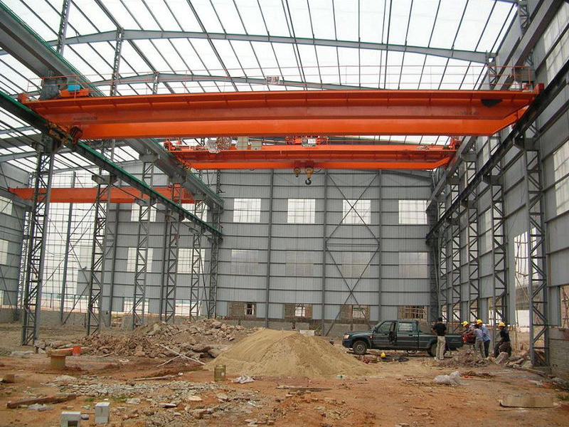
A crane runway is the fixed structure a top-running or underhung bridge crane travels along. Its job is to carry the crane, guide its motion, and pass every force into the building. It is made of a handful of components that each do a specific job:
- Runway beams: the two parallel horizontal beams that span between supports and carry the crane’s wheel loads along their length.
- Rails: the steel rails mounted on top of the runway beams (for top-running cranes), which the crane wheels actually run on.
- Supports: the columns, brackets, or building steel that hold the runway beams at the correct height and transfer the load down to the foundations.
- Rail anchoring: the clips or fasteners that hold the rail to the beam against movement while allowing thermal expansion.
- End stops and bumpers: the devices at each end of the runway that stop the crane safely at the limit of travel.
How the Load Travels
Follow a single lift through the system. The load hangs from the hook, which loads the hoist, which loads the bridge girder, which delivers the force through the end trucks and wheels onto the rails. The rails pass it to the runway beams, the beams pass it to the columns or brackets, and the columns pass it into the foundations and the ground. Every component in that chain must be sized for the force it carries — and the runway design is the part of that chain between the wheels and the building.
Takeaway: A runway is a load path from the crane wheel to the ground. Design every link — rail, beam, support, foundation — for the forces that actually reach it.
Runway Beam Selection
The runway beam is the workhorse of the system. It carries the moving wheel loads along its length, and its size is driven by span, load, and how much it is allowed to deflect.
What the Beam Must Carry
A runway beam does not carry a static, evenly spread load. It carries concentrated, moving wheel loads that shift position as the crane travels, plus dynamic effects from lifting, acceleration, and braking. That combination — moving point loads with impact — makes runway beam design more demanding than a simple floor beam of the same span.
The beam must handle three things at once:
- Vertical load: the crane’s dead weight plus the rated load plus rigging, delivered through the wheels.
- Lateral load: side forces from crane travel, acceleration, and slight skew, acting horizontally across the top of the beam.
- Longitudinal load: braking and acceleration forces acting along the length of the runway.
A beam sized only for the vertical load, ignoring the lateral and longitudinal forces, is under-designed — and lateral forces in particular are what fatigue the top flange and connections over time.
Beam Types
Two beam arrangements cover most runways:
- Standard rolled sections (wide-flange beams): economical and quick to source, suited to shorter spans and moderate loads. Where the lateral load is significant, a channel or cap plate is often added to the top flange to carry the horizontal forces.
- Fabricated (built-up) girders: custom plate girders or box sections for longer spans and heavier loads, engineered to control deflection where a rolled section cannot.
The heavier the crane and the longer the span, the more the design moves from a rolled section toward a fabricated girder.
Takeaway: Size the runway beam for moving wheel loads plus lateral and longitudinal forces — not a static distributed load. Rolled sections suit short, moderate runs; fabricated girders carry the long, heavy ones.
Rail Selection
The rail is the surface the crane wheels run on, and matching it to the wheel load is central to even wear and long life.
Why the Rail Matters
The rail takes the concentrated contact force of each crane wheel and spreads it into the runway beam below. Too light a rail for the wheel load, and the rail head wears rapidly, deforms, and transmits a rougher ride into the beam. The right rail carries the wheel load comfortably, wears slowly, and keeps the crane tracking true.
Types of Rail
Three rail options appear on runway designs:
- Crane rail (A-series / heavy rail): purpose-made crane rail with a wide head and foot, designed for high wheel loads and heavy duty. The standard for medium and heavy cranes.
- Square or rectangular bar: a simple bar stock rail, economical for lighter cranes with lower wheel loads and shorter spans.
- Standard train rail (ASCE / flat-bottom): sometimes used, though its profile is optimized for railway wheels rather than crane wheels, so it is best matched carefully to the application.
Matching Rail to Wheel Load
The rail size follows the crane’s maximum wheel load and duty class. A heavy, high-cycle crane needs a substantial crane rail with a wide head to spread the contact stress; a light, occasional-use crane can run on bar stock. Under-specify the rail and you get rapid head wear and a rough-running crane; over-specify and you pay for steel you do not need. Confirm the rail size against the crane’s actual wheel loads, which the crane supplier provides — a point worth pinning down early in the overhead crane buying guide stage, since the crane and its runway must be specified together.
Takeaway: Match the rail to the maximum wheel load and duty class. Crane rail for heavy duty, bar stock for light — and always size it from the supplier’s real wheel-load figures.
CMAA and ASME B30.2 Alignment Tolerances
Alignment is where a runway design succeeds or fails in service. A beam and rail sized correctly still run badly if the two rails are not straight, level, and parallel within tolerance. The consensus standards define exactly how tight that tolerance must be.
The Governing Standards
- ASME B30.2 is the safety standard for overhead and gantry cranes, covering the runway as part of the crane system.
- CMAA Specification No. 70 defines crane classification, design, and the runway alignment criteria the installation must meet.
Design and build to these, and you have a defensible, verifiable standard for the runway.
The Alignment Criteria
The critical runway tolerances come from CMAA Specification No. 70:
- Track gauge (span between rail centrelines): within ±3mm of nominal at any point along the runway.
- Elevation difference between the two rails at any cross-section: ±10mm maximum.
- Rail straightness (horizontal): within ±2mm in any 10-metre length.
- Rail waviness (vertical): within ±2mm in any 10-metre length.
- Rail joint step: no more than 0.5mm vertical step at any joint.
Why Each Tolerance Matters
Each tolerance targets a specific failure mode. Gauge error too wide or narrow forces the wheel flanges against the rail, wearing them and skewing the crane. Elevation difference between rails makes the crane run cross-level, loading one side harder. Straightness and waviness errors make the crane weave and bounce as it travels. And a rail joint step becomes a hammer blow on every wheel pass, wearing the wheel and cracking the beam beneath it over time.
These are not aspirational targets — they are the acceptance criteria that must be surveyed and confirmed before the crane enters service. The full alignment survey and how it is verified on site is covered in detail in the overhead crane installation guide.
Takeaway: Design to CMAA gauge, elevation, straightness, waviness, and joint-step tolerances. These criteria decide whether the crane tracks straight and wears evenly, and they must be surveyed and confirmed, not assumed.
Span and Deflection Considerations
Span — the distance the runway beam bridges between supports — is the single factor that most shapes the beam design, because deflection grows sharply as span increases.
What Deflection Is and Why It Matters
Deflection is how far the beam bends under the crane’s load. Some deflection is normal and expected, but too much causes real problems: the crane runs into a shallow valley at midspan, the wheels labor and skew, the ride roughens, and over thousands of cycles the beam fatigues. Controlling deflection is a core goal of runway beam design.
The Deflection Limit
Runway beams are designed to a deflection limit expressed as a fraction of the span. A common vertical deflection limit for crane runway beams is span divided by 600 (L/600), though the exact figure depends on the crane’s duty class and the applicable code — heavier duty classes call for stiffer beams and tighter deflection limits.
The relationship is direct: for a given beam, deflection increases rapidly as the span grows. Doubling the span far more than doubles the deflection, which is why a longer runway needs a much deeper, stronger beam to stay within the same limit.
Controlling Deflection
Where a span produces too much deflection, you have three options:
- Add intermediate supports to shorten the effective span, if the building layout allows.
- Use a deeper or heavier beam — a fabricated girder rather than a rolled section for long spans.
- Reduce the span where the layout permits, though this is often fixed by the building.
Also account for lateral deflection — the horizontal bending from side forces — which has its own, usually tighter, limit. A beam stiff enough vertically can still flex too much sideways if the lateral load was underestimated.
Takeaway: Span drives deflection, and deflection drives beam size. Design to a deflection limit like L/600 scaled to duty class, and control long spans with a deeper girder or intermediate supports.
Building Structure Load Requirements
A runway does not float. Every force it carries lands on your building — the columns, brackets, and foundations that hold it up. Verifying that the structure can take those loads is one of the most important, and most overlooked, steps in runway design.
What the Structure Must Carry
The runway delivers a set of loads into the supporting structure at each support point:
- Vertical load: the full weight of the crane, load, rigging, rail, and runway beam, delivered down through the columns to the foundations.
- Lateral load: the horizontal side forces from crane travel, pushing sideways on the columns and their connections.
- Longitudinal load: braking and acceleration forces acting along the runway, which must be resisted by bracing.
These are concentrated, dynamic loads, not static ones — and a building frame designed only for its own roof and wall loads may not accept them without reinforcement.
Columns and Their Connections
For a top-running crane, the runway beams typically sit on brackets attached to the building columns, or on dedicated crane columns. Both the columns and the bracket connections must be sized for the vertical and lateral crane loads. The lateral forces in particular demand attention, because they apply a bending moment to the column that its original design may not have allowed for.
Foundations
The columns pass their loads into the foundations, which must carry the combined vertical and lateral forces into the ground within the soil’s bearing capacity. On heavy cranes, or where the ground is poor, the foundations may need to be larger or deeper than the building’s standard footings — a cost that belongs in the project from the start.
Bracing
Longitudinal forces from braking and acceleration are resisted by bracing in the plane of the runway. Without adequate bracing, the whole runway can sway along its length under repeated braking, loosening connections over time.
Confirm the structural capacity with a structural engineer before finalizing the runway, and put any reinforcement into the budget early. This structural verification also underpins the safe operation covered in the overhead crane safety and OSHA compliance guide — a runway on an under-designed structure is a safety issue, not just a performance one.
Takeaway: The runway loads your columns, connections, foundations, and bracing with concentrated vertical, lateral, and longitudinal forces. Verify the structure can carry them all, and budget any reinforcement from the start.
Rail Anchoring Methods
How the rail attaches to the runway beam decides whether it stays put, stays aligned, and survives thermal cycling. This detail is small but decisive.
The Two Demands on Rail Anchoring
The rail anchoring must do two things that pull in opposite directions:
- Hold the rail firmly against vertical and lateral movement, so it does not creep, shift, or lift under the wheel loads.
- Allow the rail to expand and contract freely along its length as temperature changes, without building up compressive stress.
The correct method — a rail clip system — achieves both. The clips grip the rail foot against vertical and lateral movement while still letting the rail slide longitudinally as it expands and contracts.
Clip Anchoring Done Right
For a clip system to work over decades:
- Set the clip spacing to the design interval, commonly 600 to 750mm indoors, closer where duty is heavy.
- Torque the clips to specification so they grip the rail foot consistently — too loose and the rail creeps, too tight and it cannot move thermally.
- Use the correct clip type for the rail profile, whether a rigid clip or a spring/adjustable clip that allows fine lateral adjustment during alignment.
Why Welding the Rail Solid Is Wrong
The single most damaging rail anchoring mistake is welding the rail solid to the beam. It seems robust, but it locks in the thermal expansion the rail must be free to accommodate. Over a few seasons of heating and cooling, the compressive stress builds until the rail buckles into humps and lifts off the beam — leaving a wavy, damaged rail that is expensive to correct. Always clamp with clips; never weld a running crane rail solid.
Takeaway: Anchor the rail with a clip system that grips it against vertical and lateral movement while allowing thermal expansion. Set the spacing and torque to spec, and never weld the rail solid.
End Stops and Bumpers
At each end of the runway, the crane must be stopped safely at the limit of its travel. End stops and bumpers are the last line of defense against the crane running off the rail.
What They Do
- End stops are physical barriers fixed at each end of the runway that the crane cannot travel past. They are the hard limit of travel.
- Bumpers are the energy-absorbing devices mounted on the crane or the end stop that cushion the impact if the crane reaches the end of travel. They absorb the kinetic energy of the moving crane so the stop is a controlled deceleration rather than a sudden crash.
Both work together with the crane’s electrical travel limit switches, which slow and stop the crane before it ever reaches the bumpers under normal operation. The bumpers and end stops are the mechanical backup for when the limit switches or the operator fail.
Sizing the Bumpers
Bumpers must be sized for the crane’s weight and travel speed, because the kinetic energy they must absorb grows with both. A heavy crane traveling fast carries far more energy into the bumper than a light, slow one. Common bumper types include rubber, cellular polyurethane, and hydraulic units, chosen by the energy they must dissipate. Under-size the bumper and it bottoms out, transferring a hard shock into the crane and the end stop.
Placement
End stops must be positioned so the crane stops with the correct clearance at each end, and so both ends of the bridge reach their stops squarely — a crane that hits one stop before the other skews at the moment of impact. Confirm the end stop and bumper arrangement against the crane’s travel speed, weight, and required stopping clearance.
Takeaway: End stops halt the crane and bumpers absorb the impact, backing up the travel limit switches. Size the bumpers to the crane’s weight and speed, and place the stops for square, correctly-cleared stopping at both ends.
Common Runway Design Mistakes
Most runways that give trouble were let down by a handful of avoidable errors. Knowing them upfront is the cheapest protection you can buy.
Mistake 1: Sizing the Beam for Static Load Only
The runway beam is designed as if it carries a static, distributed load, ignoring the moving wheel loads, impact, and lateral forces. It deflects too far, flexes sideways, and fatigues at the top flange.
Prevention: Design the beam for concentrated moving wheel loads plus dynamic impact plus lateral and longitudinal forces, to the correct deflection limit for the duty class.
Mistake 2: Underestimating Deflection on a Long Span
A rolled section is stretched across a long span to save cost, and the resulting deflection makes the crane run into a valley at midspan and skew.
Prevention: Design to a deflection limit like L/600, and use a deeper girder or intermediate supports where the span demands it.
Mistake 3: Skipping the Building Structure Check
The runway is designed and ordered before anyone confirms the columns, connections, and foundations can carry the concentrated vertical and lateral crane loads. Reinforcement then surfaces as an unbudgeted surprise.
Prevention: Verify the supporting structure with a structural engineer for all crane loads, and budget any reinforcement from the start.
Mistake 4: Welding the Rail to the Beam
The rail is welded solid instead of clipped, so thermal expansion has nowhere to go and the rail buckles into humps over a few seasons.
Prevention: Anchor the rail with a clip system that grips it while allowing longitudinal thermal movement.
Mistake 5: Ignoring Alignment Tolerances in Design
The runway is designed without specifying the CMAA alignment tolerances, so the installer has no clear target and the crane ends up on rails that are out of gauge, out of level, or wavy.
Prevention: Specify the CMAA gauge, elevation, straightness, waviness, and joint-step tolerances in the design, and require an as-installed survey confirming them.
Mistake 6: Neglecting Lateral and Longitudinal Forces
The design accounts for vertical load but underestimates the side forces from travel and the braking forces along the runway, so the columns flex and the runway sways.
Prevention: Include lateral and longitudinal crane loads in the design of the beams, columns, connections, and bracing.
Mistake 7: Undersizing or Misplacing End Stops and Bumpers
The bumpers are too small for the crane’s weight and speed, or the end stops are placed so the crane hits one before the other. The stop becomes a hard shock or a skewing impact.
Prevention: Size bumpers to the crane’s kinetic energy and place end stops for square, correctly-cleared stopping at both ends.
Takeaway: Almost every runway problem traces back to a beam sized for static load, an ignored deflection limit, an unchecked structure, a welded rail, or missing tolerances. Close those gaps and you close most of your future trouble.
Frequently Asked Questions
Q: What is an overhead crane runway?
An overhead crane runway is the fixed structure a bridge crane travels along. It consists of two parallel runway beams that span between supports, rails mounted on top of the beams for the crane wheels to run on, the columns or brackets that hold the beams at height, the clips that anchor the rail, and the end stops and bumpers at each end. The runway carries every load the crane lifts, guides its travel, and transfers all the forces into the building structure and foundations.
Q: How do I size a crane runway beam?
Size the runway beam for the concentrated, moving wheel loads the crane delivers — not a static distributed load — plus dynamic impact from lifting and braking, and the lateral and longitudinal forces from travel. The beam must also stay within a deflection limit, commonly span divided by 600 (L/600) scaled to the crane’s duty class. Short, moderate runs may use a standard rolled section (often with a channel on the top flange for lateral load), while long or heavy runs need a fabricated girder. The crane supplier’s wheel-load figures are the essential starting point.
Q: What are the CMAA alignment tolerances for a crane runway?
Per CMAA Specification No. 70: track gauge within ±3mm of nominal at any point, elevation difference between the two rails within ±10mm at any cross-section, rail straightness within ±2mm in any 10 metres, rail waviness within ±2mm in any 10 metres, and rail joint steps no greater than 0.5mm. These tolerances control flange wear, crane skew, ride smoothness, and beam fatigue. They should be specified in the design and confirmed with an as-installed survey before the crane enters service.
Q: What deflection limit applies to a crane runway beam?
A common vertical deflection limit for crane runway beams is span divided by 600 (L/600), though the exact figure depends on the crane’s duty class and the applicable code, with heavier duty classes calling for stiffer beams and tighter limits. Lateral deflection from side forces has its own, usually tighter, limit too. Controlling deflection matters because excessive bending makes the crane run into a valley at midspan, causes skew and rough travel, and fatigues the beam over thousands of cycles.
Q: Does my building need reinforcement for a crane runway?
Possibly — it depends on the crane and the existing structure. A runway delivers concentrated vertical, lateral, and longitudinal loads into the columns, their connections, the foundations, and the bracing at each support point. A building frame designed only for its roof and wall loads may not accept these crane forces without reinforcement, and the lateral forces in particular apply bending moments the original columns may not allow for. Have a structural engineer verify the structure for all crane loads before finalizing the runway, and budget any reinforcement from the start.
Q: Why can’t a crane rail be welded directly to the runway beam?
Because the rail expands and contracts with temperature, and a solid weld leaves that thermal movement nowhere to go. Over a few seasons of heating and cooling, compressive stress builds until the rail buckles into humps and lifts off the beam, leaving a wavy, damaged rail that is expensive to correct. The right method is a rail clip system: the clips grip the rail foot firmly against vertical and lateral movement while still allowing it to slide longitudinally as it expands. Always clamp with clips, never weld a running crane rail solid.
Q: What is the purpose of end stops and bumpers on a runway?
End stops are physical barriers at each end of the runway that the crane cannot travel past, and bumpers are energy-absorbing devices that cushion the impact if the crane reaches the end of travel. Together they are the mechanical backup to the crane’s electrical travel limit switches, which slow and stop the crane before it reaches the bumpers under normal operation. Bumpers must be sized to the crane’s weight and travel speed, since the kinetic energy they absorb grows with both, and end stops must be placed so the crane stops squarely with the correct clearance at each end.
Q: Should the runway be designed together with the crane?
Yes. The crane and its runway are a single system and must be specified together. The crane’s rated capacity, span, duty class, wheel loads, weight, and travel speed all drive the runway beam size, rail selection, alignment tolerances, structural loads, and bumper sizing. Designing the runway in isolation — or ordering the crane before checking the runway and building structure — is a common and costly error. Confirm the crane specification and the runway design as one coordinated package.